Salt Spray Testing: Standards, SOP, Calibration & ROI
Want to verify that your surface treatments will survive harsh operating environments before shipping to demanding clients? Accelerated corrosion verification gives quality teams the baseline data needed to validate finishes and secure compliance across automotive, aerospace, and industrial hardware.
Below, we break down ASTM B117 vs ISO 9227, the standard salt spray test procedure, and chamber calibration.
Key Takeaways
- Core Standards: ASTM B117 and ISO 9227 share baseline Neutral Salt Spray parameters (5% NaCl at 35°C), but ISO 9227 mandates reference panel mass-loss verification and codifies acetic (AASS) and copper-accelerated (CASS) methods.
- Procedural Accuracy: Repeatable results require high-purity deionized water (conductivity under 20 µS/cm), strict sample tilt angles (15° to 30°), and continuous thermal control without frequent lid openings.
- Calibration Metrics: Routine calibration of internal temperatures (35°C), fog collection rates (1.0 to 2.0 mL/h per 80 cm²), and atomizing air pressure keeps testing fully audit-compliant.
- Operational Control: Running testing in-house eliminates multi-week commercial laboratory queues, shortens R&D feedback loops, and provides immediate quality containment on production lines.
Salt Spray Test Standards: ASTM B117 vs. ISO 9227
A salt spray test standard provides a controlled testing framework that produces a dense, heated saline fog inside a sealed testing enclosure. By maintaining stable thermal conditions, steady atomization, precise solution chemistry, and verified collection volumes, quality control teams can evaluate material resilience in days or weeks rather than waiting years for field feedback.
ASTM B117: North American Operating Practice
The ASTM B117 salt spray test (Standard Practice for Operating Salt Spray (Fog) Apparatus) remains the widely accepted standard across North American manufacturing facilities. It defines the operational parameters required to maintain a continuous Neutral Salt Spray (NSS) environment at 35°C (95°F) with a 5% sodium chloride solution.
In our view, a frequent point of confusion is treating this standard as a pass/fail determination; ASTM B117 defines the environmental conditions, while your customer’s engineering drawing must specify the required hours of exposure and acceptable cosmetic thresholds.
ISO 9227: Global Multi-Method Framework
The ISO 9227 salt spray test standard (Corrosion tests in artificial atmospheres: Salt spray tests) is the primary international document used throughout European, Asian, and global automotive supply chains. Rather than limiting the scope to a single neutral fog, it establishes three distinct testing methods within one standard:
- NSS (Neutral Salt Spray): The baseline method for raw metals, zinc plating, and powder coatings at pH 6.5 to 7.2 and 35°C.
- AASS (Acetic Acid Salt Spray): An acidified solution containing glacial acetic acid at pH 3.1 to 3.3 and 35°C, developed specifically for decorative multi-layer copper-nickel-chromium finishes.
- CASS (Copper-Accelerated Acetic Acid Salt Spray): An aggressive mixture containing copper chloride and acetic acid operating at an elevated 50°C to evaluate high-durability anodized aluminum and automotive trim.
ASTM B117 vs. ISO 9227 Comparison & Regional Mandates
When comparing ASTM b117 vs ISO 9227 (or reviewing ISO 9227 vs ASTM b117 for international contracts), both standards specify a 5% NaCl solution and comparable chamber operating parameters, allowing parallel calibration under both protocols. However, critical procedural and reporting differences exist between the two.
| Parameter | ASTM B117 (NSS) | ISO 9227 (NSS) | ISO 9227 (AASS / CASS) |
|---|---|---|---|
| Primary Region | North America / Global | Global / Europe / Asia | Global Automotive & Aerospace |
| Document Scope | Cabinet operating practice | Cabinet setup + 3 distinct methods + validation | Specialized accelerated methods |
| Chamber Temperature | 35°C ± 2°C (95°F) | 35°C ± 2°C | AASS: 35°C / CASS: 50°C |
| Salt Concentration | 5% ± 1% NaCl (50 ± 5 g/L) | 50 ± 5 g/L NaCl | 50 ± 5 g/L NaCl (+ additives) |
| Collected Mist pH | 6.5 to 7.2 | 6.5 to 7.2 | AASS: 3.1 to 3.3 / CASS: 3.1 to 3.3 |
| Collection Rate | 1.0 to 2.0 mL/h per 80 cm² | 1.0 to 2.0 mL/h per 80 cm² | 1.0 to 2.0 mL/h per 80 cm² |
| Reference Panel Type | Cold-rolled SAE 1008 carbon steel | CR4 steel plate or zinc plate | CR4 steel or zinc plate |
| Panel Preparation | Untaped edges permitted | Back and edges taped | Back and edges taped |
| Mass-Loss Reporting | Total mass loss to 1 mg accuracy | Mass loss normalized per unit area | Mass loss per unit area (g/m²) |
| Reproducibility (CV) | 12.7% coefficient of variation | 14.5% coefficient of variation | Method-specific variability |
Inter-laboratory round-robin data indicate that ASTM B117 achieves slightly tighter reproducibility, with a coefficient of variation of 12.7% versus 14.5% for ISO 9227. However, ISO 9227's requirement to normalize mass loss per unit surface area provides more directly comparable corrosion rate data across varying coupon dimensions.
In North American manufacturing, supplier contracts frequently bridge the gap between classic baseline standards and OEM-specific mandates. For instance, automotive tier suppliers across the Detroit, Windsor, and Southern Ontario manufacturing corridor routinely cross-reference ASTM B117 with cyclic protocols like General Motors (GMW 14872), Ford (CETP 00.00-L-467), and SAE J2334.
Similarly, aerospace suppliers across Washington state, California, and the Montreal aerospace cluster look to ASTM B117 alongside defense standards like MIL-STD-810 (Method 509) and MIL-DTL-5541 for conversion-coated aluminum and cadmium-replacement hardware.
Step-by-Step Salt Spray Test Procedure
Running a dependable salt spray test procedure requires strict process discipline. We view testing consistency as an interconnected sequence where small oversights during sample preparation directly compromise the final test data.
Step 1: Specimen Preparation and Edge Masking
Surface Cleaning: Clean all test coupons and production parts using a mild solvent or alcohol wipe to remove machining fluids, oils, and fingerprints without affecting the protective surface layer. Edge Protection: Seal all unplated mounting contact points, laser-cut edges, and drilled holes with non-corrosive wax, heavy lacquer, or vinyl masking tape, as unmasked raw edges corrode early and spread rust across the coated face. Scribe Scoring: If evaluating coating creep along a scratch, scribe the surface cleanly using a standardized tool per ISO 17872 or ASTM D1654.
Step 2: Saline Solution Chemistry and pH Verification
Solution Purity: Dissolve high-purity sodium chloride (<0.1% sodium iodide and minimal trace contaminants) in deionized or distilled water with an electrical conductivity below 20 µS/cm at 25°C. Target Density: Maintain a concentration of 50 ± 5 g/L, which yields a specific gravity between 1.029 and 1.036 at 25°C. pH Control: Check the baseline pH at 25°C so that the collected fog condensate stays strictly within the 6.5 to 7.2 range for NSS testing.
Step 3: Specimen Racking and Tilt Angle
Fixture Material: Place specimens on non-metallic, acid-resistant composite racks to prevent galvanic reactions, ensuring samples avoid contact with one another. Test Orientation: Angle critical test faces between 15° and 30° from vertical, or 20° ± 5° for ISO 9227 and ASTM B117 reference panels. Airflow Clearance: Space parts properly parallel to the main direction of fog flow, making sure that saline runoff from higher shelves never drips onto components below.
Step 4: Environmental Execution and Cycle Duration
Thermal Balancing: Bring the exposure chamber up to 35°C and pre-heat the air saturation tower to 45°C–47°C with an atomizing air pressure regulated between 70 and 170 kPa (0.7 to 1.7 bar, or 10 to 25 psi) to ensure full humidification and prevent temperature drops during nozzle expansion.
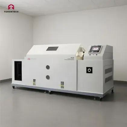
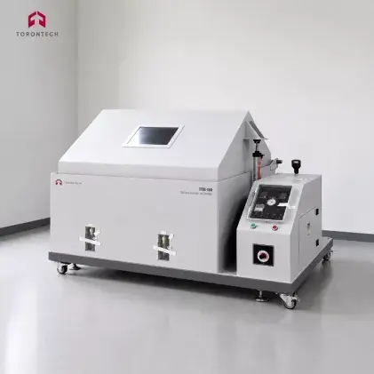
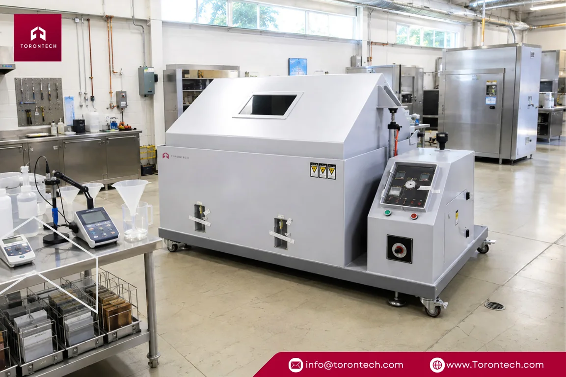
Automated Controls: Modern testing setups, such as the Torontech TTSS Series, incorporate programmable digital timers that manage continuous 500-hour or 1,000-hour test runs without requiring manual supervision. Chamber Maintenance: Testing cabinets fabricated with compression-molded reinforced plastic or high-grade PVC shells simplify post-test maintenance, as their acid-proof surfaces wipe clean easily between cycles.
Step 5: Post-Exposure Cleaning and Quantitative Evaluation
Residue Rinsing: Remove the specimens, rinse them gently under warm running tap water at approximately 38°C to clear away dried salt deposits, and dry them immediately using clean air.
Chemical Stripping: Remove corrosion products using recognized chemical treatments, such as an analytical cleaning solution per ASTM G1 for steel or a chromic acid mixture for light alloys. Degradation Rating: Measure weight loss on an analytical balance with 0.1 mg accuracy, and rate cosmetic degradation against recognized visual appearance standards (ISO 10289, ASTM D714 for blistering, ASTM D610 for surface rusting, and ASTM D1654 for scribe creep) or automated image analysis.
How to Calibrate a Salt Spray Chamber & Prevent Common Errors
To satisfy ISO/IEC 17025 laboratory audits and maintain internal quality records, technicians must know how to calibrate a salt spray chamber across all primary operating parameters.
Core Sub-System Calibration Protocols
- Temperature Mapping: Position calibrated temperature sensors throughout the internal workspace to confirm the chamber maintains 35°C ± 2°C uniformly across all racking positions during extended test runs.
- Deposition Fallout Collection: Place calibrated 80 cm² collection funnels over graduated cylinders in at least two separate racking areas to verify that deposition rates settle between 1.0 and 2.0 mL/hour per funnel across a continuous 16-hour evaluation.
- Salinity and pH Verification: Measure specific gravity with a calibrated hydrometer or digital refractometer (1.0255 to 1.0400 at 25°C), and calibrate your digital pH meter using fresh 4.0, 7.0, and 10.0 buffer solutions before logging readings from collected mist.
- Atomizing Air Regulation: Maintain the compressed air supply between 70 and 170 kPa (10 to 25 psi), with saturation tower water heated to approximately 47°C, periodically cleaning nozzles to preserve an even dispersion pattern.
- Steel Mass-Loss Verification: Expose standard carbon steel reference coupons (SAE 1008 for ASTM B117 or CR4 for ISO 9227) for 48, 96, or 168 hours, confirming total metal loss falls within standard control boundaries (70 ± 20 g/m² for 48-hour ISO 9227 NSS) and tracking results on Shewhart control charts.
Operational Troubleshooting Guide
| Observed Issue | Probable Root Cause | Immediate Corrective Action |
|---|---|---|
| Fallout Rate Below 1.0 mL/h | Salt accumulation within the nozzle orifice or low atomizing air pressure. | Clean the nozzle using a mild descaling wash, verify line pressure is between 10 and 25 psi, and adjust the dispersion cone. |
| Collected pH Drifting Above 7.2 | Compressed air stripping dissolved carbon dioxide from the saline solution during atomization. | Verify deionized water purity (<20 µS/cm) and buffer the initial solution to pH 6.5–6.8 using dilute analytical-grade acid. |
| Crystallized Salt on Nozzle Tip | Dry compressed air absorbing moisture directly from the saline solution. | Confirm saturation tower water levels and ensure tower operating temperature is maintained 10°C to 12°C above chamber heat. |
In-House Testing ROI & Chamber Selection Guide
If your facility routinely ships samples to third-party testing laboratories, we suggest evaluating the full cost of that workflow. In addition to high invoice costs, multi-week delays create bottlenecks for product releases and process changes.
Related article: Salt Spray Chamber Buyer's Guide & Lab Checklist
Economic Case: In-House Testing vs. Contract Laboratories
| Decision Factor | Third-Party Contract Lab | In-House Test Chamber |
|---|---|---|
| Recurring Operating Expense | Recurring commercial lab fees per test cycle plus expedited freight | Low marginal cost per run (routine electricity, pure NaCl, and DI water) |
| Turnaround Time | Multi-week queue time and shipping transit delays | Immediate startup on demand |
| Engineering Agility | High cost per iteration; batching required to manage expense | Test modifications daily with immediate visual feedback |
| Production Risk | High; coating defects discovered weeks after manufacturing | Immediate detection and containment of plating/coating issues |
In our view, continuing to outsource frequent salt fog verification creates avoidable operational delays and recurring expenses. For facilities running frequent verification cycles, adding an internal test cabinet significantly reduces ongoing testing expenditures while restoring complete control over production and compliance timelines.
Continuous vs. Cyclic Test Architectures
Standard continuous salt spray chambers, such as the Torontech TTSS Series, maintain constant fog atomization and temperature to support ASTM B117, ISO 9227 (NSS, AASS, CASS), and JIS Z 2371. In contrast, combined Temperature & Humidity Salt Spray Corrosion Test Chambers automate transitions between salt fog, dry-off, condensing humidity, and ambient rest stages to execute advanced cyclic protocols like ASTM G85 (Annexes A2–A5), SAE J2334, VDA 233-102, and GMW 14872.
Related article: Salt Spray vs Cyclic Corrosion Testing Guide
Chamber Sizing and Application Matrix
| Capacity Category | Typical Sample Geometries | Target Regional Standards & Use Cases |
|---|---|---|
| Compact Enclosures (108L to 270L) | Small brackets, fasteners, connectors, and flat test coupons. | Fastener qualification and zinc-nickel plating audits for tier-1 automotive suppliers in the Midwest and Ontario. |
| Mid-Sized Floor Units (480L to 800L) | Structural hardware, stamping sub-assemblies, and industrial fixtures. | Epoxy-coated rebar and galvanized bridge guardrails mandated by US State DOTs (Caltrans, PennDOT, TxDOT) and Ontario MTO. |
| High-Capacity Units (1,000L+ & Walk-In) | Large weldments, bumper beams, and full chassis components. | Heavy agricultural machinery in the US Midwest and Canadian Prairies, commercial truck frames, and large assemblies. |
Essential Hardware Build Characteristics
We strongly advocate for non-metallic construction across both interior and exterior shells. Cabinets built from compression-molded reinforced plastic or high-grade PVC provide complete resistance to acids, alkalis, and mechanical impacts, eliminating internal corrosion issues when running aggressive CASS or AASS solutions.
Additionally, choosing systems with centralized atomizing spray towers, precision nozzles, automated water replenishment, and built-in collection funnels ensures consistent fog distribution and simplifies daily test monitoring.
Advance In-House Corrosion Testing with Torontech
Verifying coating durability against international standards is essential for maintaining client confidence and preventing costly field failures. Achieving repeatable, audit-ready data requires consistent operating procedures paired with dependable testing hardware.
At Torontech, we deliver cost-effective solutions and innovative technologies that help quality control teams meet strict testing requirements while keeping capital investments practical.
Ready to bring corrosion testing in-house or upgrade your laboratory capacity? Explore our complete selection of Salt Spray Corrosion Test Chambers or contact the Torontech engineering team today to discuss your testing requirements and request a quotation.
References (Click to expand)
- Benítez, R., & Andrés, Ó. (2014). Diseño y construcción de una cámara de niebla salina y su uso en un estudio de recubrimientos de níquel por electrodeposición.
- Garbacz, M. (2023). Estimating the Uncertainty of the Result for Tests of Resistance to Environmental Conditions on the Example of the Method of Resistance to Neutral Salt Mist According to EN ISO 9227 / ASTM B117. Problemy Kolejnictwa: Railway Reports.
- Ishida, Y., Shitara, Y., Miki, D., Yamada, M., Murai, M., & Sakuma, N. (2022). Visualization and Quantification of Corrosion Processes during Salt Spray Tests. The Proceedings of The 9th International Conference on Intelligent Systems and Image Processing 2022.
- LeBozec, N., Hall, C., & Mélot, D. (2014). ComparISOn of Accelerated Ageing Tests as per ISO 20340 Annex a and NACE SP0108 Standards. CORROSION 2014.
- Olugbade, T., & Omiyale, B. O. (2021). Corrosion resistance of surface-conditioned 301 and 304 stainless steels by salt spray test. Analecta Technica Szegedinensia.
- Suga, S., & Suga, S. (2005). Report on the Results from the ISO/TC 156/WG 7 International Round Robin Test Programme on ISO 9227 Salt Spray Tests. Journal of The Surface Finishing Society of Japan, 56, 28-28.
- Usman, B. J., Scenini, F., & Curioni, M. (2020). Corrosion Testing of Anodized Aerospace Alloys: ComparISOn Between Immersion and Salt Spray Testing using Electrochemical Impedance Spectroscopy. Journal of The Electrochemical Society.