Manual vs Automatic MFI: Which Tester Fits Your Lab?
Looking to Improve Laboratory Testing Throughput and Precision Without Overspending on Capital Equipment?
In plastics processing and compounding, reliable Melt Flow Index tracking ensures consistent quality and dependable lot releases. This guide breaks down manual vs automatic melt flow index testers to help you select the ideal setup for your facility.
At a Glance: Manual vs Automatic Melt Flow Index Testers
For busy lab directors who need the bottom line immediately, this quick-reference matrix summarizes the core operational and analytical differences between manual and automated systems:
| Operational Consideration | Procedure A (Mass-Based / Manual Cutting) | Procedure B (Sensor-Based / Automated Displacement) |
|---|---|---|
| Load Application | Operator places standard test masses on piston | Operator places standard test masses on piston |
| Timing Mechanism | Handheld stopwatch or automated timer | Electronic displacement sensor zones |
| Sample Collection | Physical strand cutting and analytical scale transfer | Continuous optical tracking without physical cuts |
| Variance in Research | Timing and cutting variance across runs | Under 2% error reported for automated tracking |
| Analytical Scope | Standard MFR flow grading | MVR, melt density, and flow stability |
| Standards Compliance | ASTM D1238 Procedure A; ISO 1133-1 Method A | ASTM D1238 Procedures A, B; ISO 1133 Methods A, B |
| Technician Involvement | 12 to 18 minutes (monitoring, cutting, weighing) | 3 to 5 minutes (loading, initiating run, cleaning) |
| Data Handling | Handwritten notes or manual spreadsheet entry | Direct digital file export, display, or onboard printout |
| Capital Outlay | Budget-friendly initial cost | Moderate initial investment |
| Primary Lab Fit | Low-volume QC, incoming inspection, educational labs | Multi-shift testing, technical compounding, recycled resins |
Core Testing Mechanisms: Procedure A vs. Procedure B
To evaluate manual vs automatic melt flow index testers, we need to clarify what these labels mean in practice. In the polymer testing industry, "manual versus automatic" primarily differentiates between Procedure A (the mass-based cutting method) and Procedure B (the sensor-based volumetric displacement method).
Procedure A: Mass-Based Testing
Manual melt flow instruments run primarily on Procedure A (ASTM D1238) or Method A (ISO 1133-1).
The operator charges polymer pellets, granules, or film strips into a heated barrel, tamps the material down firmly to purge trapped air, and manually places standard test masses onto the piston. As molten polymer extrudes through the standardized tungsten carbide die, the technician monitors the preheat clock with a stopwatch and cuts extrudate segments at timed intervals.
Once the cuts are complete, the cooled polymer strands are transferred to an analytical balance. The technician records the mass manually and calculates the flow rate to report output in grams per 10 minutes (g/10 min).
Standard test conditions are governed by resin material standards rather than operator choice. The table below lists standard ASTM D1238 industry test conditions alongside the practical flow range where Procedure A mass cutting is viable:
| Thermoplastic Resin Type | Standard ASTM Test Condition | Viable Procedure A Flow Range |
|---|---|---|
| Polyethylene (PE / Standard) | 190 °C / 2.16 kg | 0.15 to 50 g/10 min |
| Polyethylene (PE / High Load - HLMI) | 190 °C / 21.6 kg | 0.15 to 50 g/10 min |
| Polypropylene (PP) | 230 °C / 2.16 kg | 0.15 to 50 g/10 min |
| Polystyrene (PS) | 200 °C / 5.0 kg | 0.15 to 50 g/10 min |
| Acrylonitrile Butadiene Styrene (ABS) | 230 °C / 3.8 kg | 0.15 to 50 g/10 min |
Both Procedure A and Procedure B execute under these exact material conditions. However, if your specific resin grade flows faster than roughly 50 g/10 min under its prescribed temperature and load, manual physical cutting becomes impractical, requiring automated Procedure B displacement tracking instead.
Procedure A remains an honest, dependable testing method that measures physical mass directly. Equipment in this category can also eliminate manual cutting inconsistencies.
For example, our tabletop ToronMFI™-A pairs microprocessor thermal regulation within ±0.5 °C with a built-in automatic scraper timed to ±0.1 seconds, giving labs repeatable timed cuts across all standard ASTM test weights without relying on a handheld razor blade.
Procedure B: Automated Displacement
Automatic melt flow testers execute Procedure B or switch between dual Procedure A and B modes, removing manual timing steps from data collection. After the sample is loaded and preheated, the test mass acts on the molten material while high-resolution optical encoders or electronic displacement sensors track the exact distance and elapsed time of piston travel over calibrated measurement zones.
From there, the onboard computer calculates the Melt Volume-Flow Rate (MVR in cm³/10 min). By programming the melt density of the resin into the software, the system converts MVR to MFR (g/10 min) without requiring sample cutting, cooling trays, or analytical balance measurements.
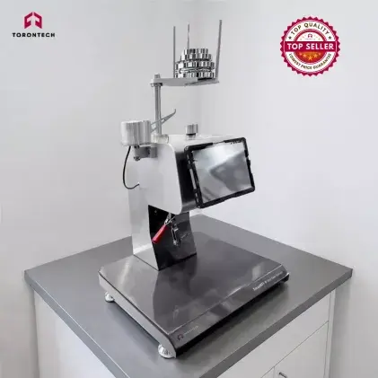
Automating the reading system shifts routine MFI equipment from a basic grading device into an advanced polymer analyzer capable of evaluating melt density, filler content, and thermal stability. Mid-range instruments such as our tabletop ToronMFI™-B demonstrate this balance in practice: they support both Procedure A and Procedure B testing, utilizing an intuitive front-panel interface and an onboard printer so operators can generate immediate physical verification tickets right at the bench.
Measurement Accuracy and Repeatability
Evaluating manual vs automatic melt flow index testers requires looking at how testing consistency impacts your production floor.
In academic literature, automated determination of melt flow rate yields test results with less than 2% error compared to manual cutting methods.
Manual testing introduces human variability through slight timing delays, uneven blade sweeps, and sample transfer discrepancies. Because of these factors, academic and industrial studies relying on manual testers typically repeat each test configuration three to five times just to smooth out human-induced error.
Round-robin MFI testing consistently reveals significant differences between independent laboratories. These variances stem from inconsistencies in equipment condition, testing environment, and operator setup: factors that standardized electronic automation directly minimizes.
Operator error during manual runs is rarely a reflection of careless staff; it is simply what happens when a technician is forced to synchronize a hand blade to a fraction of a second on a hot, continuously moving strand of molten polymer. Automation removes that physical timing pressure from the equation.
For moisture-sensitive resins such as PET, PBT, and polyamides (PA), moisture content causes poor repeatability and reproducibility regardless of instrument type. With these materials, strict control of pre-heating durations, extrusion windows, and resin drying times is critical.
Automatic testers shine here because their programmed, electronic test routines enforce identical cycle timing every single run, preventing polymers from thermally degrading inside the barrel.
Equipment Cost and Accessibility
Budget allocations often dictate equipment decisions. In the manual vs automatic MFI evaluation, each instrument class serves a distinct economic niche.
Manual MFI testers remain common across industrial processing due to their affordability, operational simplicity, and widespread market availability.
For many quality facilities, a standard Melt Flow Indexer serves as an economical alternative to a high-pressure capillary rheometer for gathering initial viscosity curves. Traditional capillary rheometry requires high capital investment, long test cycles, and specialized operators, making MFI testing a sensible first line of defense.
At the same time, recent open-source engineering initiatives have focused on developing automated MFI designs to evaluate recycled polymers economically. These systems illustrate the industry's desire to bridge the gap between low-cost manual testers and expensive commercial automation.
At Torontech, our equipment philosophy aligns with this objective: testing facilities should enjoy modern sensor precision without absorbing exorbitant brand markups.
Physical Limitations of Extrusion Plastometers
To make a well-grounded equipment choice, quality managers must recognize the physical boundaries inherent to extrusion plastometers. Both manual and automatic MFI testers share geometric constraints when evaluated against capillary rheometers.
The standard MFI barrel uses a single standardized capillary die (typically 2.095 mm diameter by 8.000 mm length) without accommodations for Bagley end corrections or Rabinowitsch shear-thinning adjustments. Because of this short capillary geometry and the absence of mathematical corrections, MFI-derived viscosity calculations run roughly 20% to 30% higher than reference data gathered on high-pressure capillary rheometers.
Furthermore, standard MFI runs examine flow exclusively at low shear rates (often below 50 s⁻¹), limiting their direct correlation to high-shear processing operations such as injection mold gate filling or high-speed extrusion.
Automation significantly improves measurement repeatability, cycle consistency, and lab throughput, but it does not alter the fundamental capillary geometry of the test. To address this boundary, advanced instruments like our ToronMFI™-V expand beyond single-point MFR values.
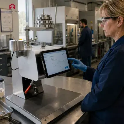
Operated via an external tablet, the system captures MFR, MVR, melt density, apparent viscosity, shear stress, and shear rate in a single run, providing a broader rheological picture while operating within standard plastometer parameters.
Automation and Predictive Modeling
Laboratory automation is connecting directly to modern factory intelligence systems. Recent research integrates digital automation with custom-built MFI hardware to ensure repeatable execution of testing cycles across long production shifts.
Machine learning algorithms trained on datasets generated by automated MFI units can predict Melt Mass-Flow Rates with an error margin of just 0.3 g/10 min (a mean absolute percentage error of 3.2%). In commercial polyethylene granulation, in-line soft sensors using XGBoost algorithms achieve predictive accuracy of R² = 0.99 for real-time MFI tracking, reducing the need for repetitive manual bench checks.
Similarly, on-line automatic rheometers mounted directly onto production extruders divert a tiny slipstream of melt through a capillary slit-die and return the sampled resin straight back to the main melt stream without manual handling. These systems produce automatic certifications of flow rate, steady shear viscosity, and melt index within minutes.
For benchtop quality control labs, choosing an automated tester equipped with digital data output establishes the foundational infrastructure needed to interface with these digital monitoring frameworks.
Practical Applications and Resin Demands
Regional industrial hubs across North America highlight distinct processing requirements, demonstrating where manual and automated systems fit best.
Recycled Plastics and PCR Compounding
Recycling facilities and compounders operating under regional post-consumer recycled (PCR) packaging mandates (such as California's SB 54, Washington State regulations, and Canadian federal packaging rules) face feedstocks with wide batch-to-batch variation in melt viscosity, moisture levels, and residual contamination.
Unpredictable flow surges disrupt manual cut timing, causing false out-of-spec rejections that can stall an entire compounding run.
An automatic melt flow index tester running Procedure B displacement tracking delivers reliable, multi-point measurement zones across every test stroke. Tracking MVR alongside MFR is critical for recycled materials because unexpected shifts in volume rate alert you to filler fluctuations or contamination before resin enters a production extruder.
This is where higher-tier models such as the ToronMFI™-D stand out, as they are engineered specifically for compounding quality control and evaluating filled versus unfilled thermoplastics by pairing automated data collection with precise volumetric displacement.
High-Flow Resins and Masterbatch
Large-scale resin synthesis and compounding hubs (such as those along the Texas and Louisiana Gulf Coast or within Alberta's Industrial Heartland) process high-output streams of polypropylene. These grades typically exhibit MFI values running from roughly 30 g/10 min for spunbond non-wovens up to 100 g/10 min for thin-wall packaging.
In contrast, specialized melt-blown filtration grades sit far above this range (typically 800 to 1,500 g/10 min) and exceed standard testing boundaries, requiring specialized ASTM D1238 Procedure C half-die setups to restrict flow.
Within the 30 to 100 g/10 min window, manual physical cutting creates severe timing discrepancies and increases operator exposure to hot resin due to high extrusion speeds. An automatic melt flow index tester with digital displacement tracking monitors rapid piston travel without physical blade passes, producing dependable numbers on materials that are impractical to test by hand.
Low-Volume Incoming Quality Control
Custom injection molders (such as Tier-2 and Tier-3 suppliers throughout the Great Lakes manufacturing corridor across Ontario and the US Midwest) frequently process certified virgin resins (like standard ABS, nylon, or polycarbonate) for interior automotive clips and brackets. These facilities often struggle to justify a complex automated system on a practical capital budget when testing only occurs two or three times a week.
A manual melt flow indexer running Procedure A (such as our ToronMFI™-A) provides full certified compliance at an accessible price point, fulfilling customer audit demands without unnecessary expense.
Financial Analysis and Return on Investment
When comparing manual vs automatic MFI, the higher initial capital expenditure of an automated system is frequently offset by daily labor savings and reduced scrap. In our financial view, the initial price difference should be evaluated as recovered technician capacity.
Consider an illustrative operational model for a compounding or processing facility running an average of 15 melt flow tests per day over a five-day work week (roughly 3,900 runs per year).
Running a manual tester via Procedure A demands roughly 15 minutes of active technician time per run for barrel packing, preheat monitoring, 3 to 4 timed cuts, cooling, analytical weighing, and manual calculations. That totals 975 hours per year dedicated purely to MFI chores.
At a fully burdened lab technician rate of 38 to 45 USD per hour (reflecting typical manufacturing payroll, benefits, and overhead across industrial centers in the US Midwest, the Carolinas, or Southern Ontario), annual testing labor cost averages 37,050 to 43,875 USD.
Running an automatic tester via Procedure B cuts active technician time down to roughly 4 minutes per run to load resin, initiate the automated cycle, and return for a quick post-test barrel cleanout. That reduces annual testing labor to 260 hours, dropping labor costs to roughly 9,880 to 11,700 USD.
Reclaimed Technician Time in Operational Models
Switching from a manual routine to automated displacement testing can put over 700 hours of skilled technician capacity back into your laboratory each year based on this model. In technical manufacturing sectors where finding and retaining qualified lab staff remains challenging, freeing up hundreds of hours lets personnel focus on analytical troubleshooting rather than babysitting a timer.
In this operational scenario, the price difference between an entry-level manual unit and an automated system can pay for itself within 6 to 9 months, even before factoring in the financial savings gained by catching out-of-spec resin lots before they reach full-scale production.
Laboratory Selection Framework
To help quality teams establish clear internal consensus, we have structured our evaluation framework into this straightforward diagnostic scorecard:
| Evaluation Factor | Procedure A (ToronMFI-A) | Dual-Mode MFI (ToronMFI-B) | Advanced Testing (ToronMFI-D / V) |
|---|---|---|---|
| Daily Test Queue | Under 5 runs per shift | 5 to 15 runs per shift | 15+ runs per shift (multi-shift) |
| ASTM Procedural Scope | Procedure A (practical standard range: 0.15 to 50 g/10 min) | Procedure A and B (dual mass and volume tracking up to 100 g/10 min) | Procedure A and B (automated volume and rheology up to 100 g/10 min) |
| Material Types | Stable, certified virgin resins | Virgin plus routine compounds | Recycled PCR, regrind, filled resins |
| Lab Staffing | Single dedicated technician | Rotating small QC team | Multi-shift, varied skill levels |
| Audit Demands | Basic internal quality logs | Standard commercial audits | Comprehensive digital reporting |
| Primary Financial Goal | Minimize upfront equipment CapEx | Balance initial cost and capability | Maximize daily labor recovery |
Note: All four ToronMFI models share the same published measurement range of 0.1 to 100 g/10 min (MFR). The practical distinction lies in which ASTM D1238 procedure, automation level, and analytical outputs each instrument provides.
Torontech ToronMFI™ Series Overview
Deciding between manual vs automatic melt flow index testers often leaves lab managers feeling cornered between inflated legacy price tags and cheap, unreliable alternatives. Traditional equipment suppliers frequently charge substantial markups for standard automation, while entry-level import options often suffer from poor thermal uniformity, flimsy construction, and questionable standards compliance.
At Torontech, we supply cost-effective solutions and innovative technologies. Operating through our North American distribution and support centers in Toronto, Ontario and Miami, Florida, we provide testing facilities across the US and Canada with durable, standards-compliant hardware backed by direct technical assistance and timely access to replacement parts.
Our lineup of ToronMFI™-Series Melt Flow Indexers / Extrusion Plastometers complies fully with ASTM D1238 and ISO 1133, offering practical configurations for varied testing environments:
ToronMFI™-A: Procedure A Testing
Designed for dependable, budget-friendly Melt Mass-Flow Rate (MFR) testing via Procedure A. Featuring an integrated microprocessor temperature controller stable within ±0.5 °C, an automated scraper timed to ±0.1 seconds, and a full set of standard test weights, it is a plug-and-play tabletop solution for raw material spot checks, incoming film and granule inspection, and cost-conscious QC labs.
ToronMFI™-B: Dual Procedure A and B Testing
A versatile tabletop model equipped to measure both MFR (Procedure A) and MVR (Procedure B). With a clear front-panel control interface and a built-in printer for immediate hard-copy documentation, the ToronMFI-B is a practical choice for growing labs that require automated volume tracking and melt density calculations without the cost of complex industrial systems.
ToronMFI™-D: Automated High-Volume Testing
Engineered for high-throughput testing queues, compounding operations, and multi-shift facilities. Exceeding baseline ISO 1133 and ASTM D1238 requirements, this model incorporates advanced thermal stability, automated data logging, and dedicated capabilities for evaluating filled versus unfilled thermoplastics and reinforcing additives.
ToronMFI™-V: Tablet-Operated Rheological Testing
Built for comprehensive material characterization, the ToronMFI-V connects to an external tablet computer with dedicated software to capture MFR, MVR, melt density, apparent viscosity, shear stress, and shear rate simultaneously in a single run.
Select Your Ideal MFI Tester with Torontech
Choosing between manual vs automatic MFI comes down to daily sample volume, polymer flow behavior, and laboratory staffing. Semi-automatic mass-measurement units provide a dependable baseline for routine spot checks, while automated displacement instruments deliver the speed, hands-off operation, and digital records required for high-throughput manufacturing.
Explore our ToronMFI™-Series Melt Flow Indexers to see how our cost-effective solutions and innovative technologies support your quality control goals. Connect with our technical specialists today for an informal consultation or to request a competitive quote.
References (Click to expand)
- (1993). industry news. Journal of Plastic Film & Sheeting, 9, 171 - 172.
- Biçen, A. O., & Çağlı, Ç. (2025). Computerized Automation and Machine Learning for Prediction of Melt Mass-Flow Rate Using Custom-Built Machine in Industrial IoT. IEEE Transactions on Industrial Informatics, 21, 9468-9479.
- Gufeng, C. (2011). Automatic Determination of Melt Flow Rates of PS and ABS. China Plastics.
- Hernández‐Fernández, J., & López‐Martínez, J. (2026). Operational Domains Governing Melt Flow Index Variability in Industrial Polypropylene Production. Polymers, 18.
- Jani, F., Hosseini, S., Sepahi, A., Torabi, F., Nasiri, H., Zadeh, A. S., Ghorbani, R., & Arani, M. H. (2026). Data‐Driven Machine Learning Framework as an In‐Line Melt Flow Index Analyzer in Polyethylene Granulation. Macromolecular Theory and Simulations, 35.
- Liu, D., Basdeo, A., Suescun Gonzalez, C., Romani, A., Boudaoud, H., Nouvel, C., Cruz Sanchez, F. C., & Pearce, J. (2024). Low-Cost Open-Source Melt Flow Index System for Distributed Recycling and Additive Manufacturing. Materials, 17.
- Locati, G., Poggio, S., & Rathenow, J. (1996). The new melt flow rate testers: Not merely graders… but powerful polymer analyzers. Polymer Testing, 15, 443-454.
- Oubellaouch, K., Pelaccia, R., Orazi, L., Pozzi, P., Carmignato, S., Bonato, N., Donati, L., Raimondi, L., & Reggiani, B. (2025). A novel experimental–numerical procedure for the rheological characterization of thermoplastic polymers applied to injection molding. The International Journal of Advanced Manufacturing Technology, 140, 5419 - 5433.
- Oubellaouch, K. (2024). A melt flow index-based approach for the viscosity curves determination. Materials Research Proceedings.
- Sholley, C. (1984). Use of the Automatic Capillary Rheometer in Quality Control.
- Su, N., Liu, X., Chen, X., Gu, J., & Bai, J. (2026). Combining response surface methodology and measurement system analysis to identify melt flow index of hygrothermal-sensitive composites. Scientific Reports, 16.
- Wilczyński, K., Buziak, K., Lewandowski, A., & Wilczyński, K. (2025). Rheology for Wood Plastic Composite Extrusion—Part 1: Laboratory vs. On-Line Rheometry. Polymers, 17.