
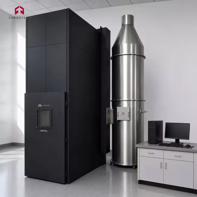
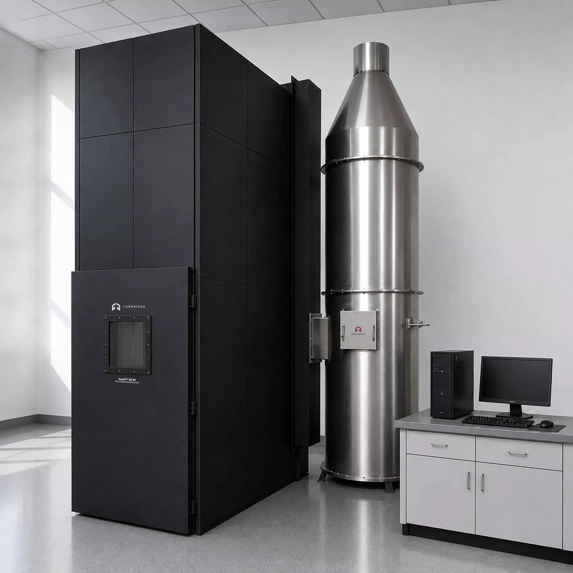
Wire and Cable Heat Release Tester
Wire and Cable Heat Release Tester - ToronFT™ HR-WC
ToronFT™ HR-WC wire cable heat release tester measures flame spread, heat release rate (HRR), total heat release (THR), total smoke production (TSP), and smoke optical density for bunched electric cables and optical fibre cables mounted on a vertical standard ladder inside a controlled combustion chamber. The instrument follows the test method defined in EN 50399, which underpins the Euroclass fire performance classification system for cables under the European Construction Products Regulation EN 50575. Cable manufacturers, testing laboratories, and notified bodies use the ToronFT™ HR-WC to qualify products for Euroclass designations from B1ca through Dca, providing the documentation needed for CE marking and Declaration of Performance.
The test chamber measures 1000 mm wide by 2000 mm deep by 4000 mm high and is constructed with an inner stainless steel wall insulated by 65 mm of thermal insulation cotton, matching the chamber geometry specified in EN 60332-3-10 on which EN 50399 is based. A ribbon-type propane burner mounted on a movable trolley serves as the ignition source, operating at either 20.5 kW for standard Euroclass tests (B2ca, Cca, Dca) or 30 kW for the more demanding B1ca tests. Combustion air enters the chamber at a controlled flow rate of 8000 ± 400 L/min through an inlet opening at the base of the front wall, ensuring a consistent oxygen supply throughout the 20-minute test. The front door carries a tempered glass observation window so the operator can monitor flame spread and cable behaviour without interrupting the sealed test environment.
All combustion products leave through an exhaust outlet at the top of the chamber and pass through an instrumented duct section that carries the full gas analysis, mass flow, and smoke density measurement package. A paramagnetic oxygen analyser and an infrared CO₂ analyser continuously sample the exhaust stream through a multi-hole probe, and the oxygen depletion method converts those readings into real-time heat release rate. The smoke optical density system measures light attenuation across the duct and feeds directly into the TSP calculation. A computer control and data acquisition system logs all channels, tracks the test timer, and produces the EN 50399 output parameters, including peak HRR (FIGRA₀.₂MJ and FIGRA₁.‰MJ fire growth indices), THR₁₀₀₀, TSP₁₀₀₀, and smoke growth rate index (SMOGRA), which feed directly into the EN 13501-6 Euroclass classification.
Wire and Cable Heat Release Tester - ToronFT™ HR-WC Applications
The ToronFT™ HR-WC covers the full scope of fire performance testing for bundled cables and optical fibre cables in construction applications. It is used wherever EN 50399 and EN 50575 test data are required for product classification, certification, or regulatory compliance.
- Cable Manufacturers Seeking CE Marking: Euroclass fire performance testing of power, control, and communication cables for Declarations of Performance under EN 50575, covering classes B1ca through Dca for EU market access.
- Accredited Testing and Notified Laboratories: third-party EN 50399 testing on behalf of cable manufacturers pursuing Euroclass certification, including generation of the test reports required by notified bodies for AVCP System 1+ products.
- Optical Fibre Cable Producers: flame spread, heat release, and smoke production testing of fibre optic cables installed in buildings and civil engineering works, for Euroclass classification under EN 50575.
- Building and Construction Material Regulators: verification testing of cable products supplied for critical installations in hospitals, schools, airports, data centres, and public buildings where minimum Euroclass ratings are specified.
- Cable R&D and Product Development Laboratories: screening of jacket compound formulations, filler materials, and fire-retardant additive systems during product development to optimise heat release and smoke performance ahead of formal classification testing.
- Compliance and Quality Assurance Teams: routine production monitoring of cable fire performance to confirm that manufactured products continue to meet the declared Euroclass, with HRR and smoke data stored for audit and traceability.
- Fire Safety Research Institutions: academic and applied investigation of combustion behaviour of bundled cable assemblies under medium-scale fire exposure, with full calorimetric and photometric data output for analysis.
- Export Certification for European Markets: testing of cables manufactured outside the EU to EN 50399 for export qualification, enabling manufacturers in North America, Asia, and elsewhere to obtain EN 50575-based Euroclass designations for EU sales.
Standards
The ToronFT™ HR-WC satisfies the apparatus, instrumentation, and test procedure requirements of the following international and European standards for cable fire performance testing.
- EN 50399 - Common Test Methods for Cables Under Fire Conditions: Heat Release and Smoke Production Measurement on Cables During Flame Spread Test - Test Apparatus, Procedures, Results
- EN 50575 - Power, Control and Communication Cables: Cables for General Applications in Construction Works Subject to Reaction to Fire Requirements
Wire and Cable Heat Release Tester - ToronFT™ HR-WC Key Features
The ToronFT™ HR-WC combines a full-size EN 50399-compliant combustion chamber with integrated gas analysis, optical smoke measurement, and computerised data processing in a single system designed for professional cable fire performance testing.
- Full-Compliance EN 50399 Chamber Geometry: 1000 mm × 2000 mm × 4000 mm, ensuring test results are directly comparable with accredited reference data and accepted by notified bodies for Euroclass classification.
- Dual Burner Power Levels for Full Euroclass Coverage: the propane ribbon burner operates at 20.5 kW for standard B2ca, Cca, and Dca tests and at 30 kW for B1ca qualification, allowing a single instrument to cover the complete EN 50575 Euroclass range without hardware changes.
- Paramagnetic Oxygen Analyser for Primary HRR: a paramagnetic O₂ analyser with a measurement range of 0 to 25% continuously monitors exhaust oxygen concentration; temperature and pressure compensation are applied to the output, giving the high-accuracy signal needed for the oxygen depletion HRR calculation.
- Infrared CO₂ Analyser for Secondary HRR Correction: a dedicated infrared CO₂ analyser (range 0 to 10%) provides the carbon dioxide signal required by the EN 50399 heat release formula, correcting for incomplete combustion effects and improving overall HRR accuracy.
- Three-Stage Gas Pre-treatment System: combustion gases pass through a soot filter, refrigerant cold trap, and drying column before reaching the analysers, removing particulates and moisture that would otherwise damage the sensors and introduce measurement error.
- White-Light Smoke Optical Density System: a photometric smoke measurement unit operating at approximately 2900 K colour temperature measures light attenuation across the duct, computing specific optical density in real time for TSP and SMOGRA calculation.
- Stainless Steel Bi-directional Mass Flow Probe: the duct flow probe measures the differential pressure profile across the exhaust stream and combines with three Type K duct thermocouples to compute exhaust volume flow, the denominator in both the HRR and SPR calculations.
- Controlled Air Supply at 8000 ± 400 L/min: a forced-air supply system delivers combustion air through the standardised 800 mm × 400 mm inlet aperture at the defined rate, maintaining the oxygen environment specified by EN 50399 throughout the test.
- Sealed Insulated Chamber Construction: the inner wall of 1.5 mm stainless steel with 65 mm insulation cotton and heat transfer coefficient of approximately 0.7 W·m⁻²·K⁻¹ eliminates ambient heat losses that would reduce measured HRR, while the sealed door prevents combustion gas leakage into the laboratory.
- Tempered Glass Observation Window: the front door carries a full-height tempered glass window so the operator monitors flame spread, dripping behaviour, and cable collapse in real time without opening the chamber or disturbing the sealed test atmosphere.
- Computerised Data Acquisition with EN 50399 Output: the control software logs all measurement channels, computes FIGRA₀.₂MJ, FIGRA₁.‰MJ, THR₁₀₀₀, TSP₁₀₀₀, and SMOGRA indices directly, and produces formatted test reports ready for submission to notified bodies or inclusion in a Declaration of Performance file.
- Steel Ladder Access to Chamber Top: an access ladder and handrail system on the exterior chamber wall provides safe access to the roof of the 4 m chamber for specimen loading, equipment inspection, and exhaust duct connections.
Theory and Method
The EN 50399 test method mounts a defined quantity of cable or optical fibre cable onto a 500 mm wide vertical steel ladder inside the sealed chamber, applies a ribbon propane flame at the base for 20 minutes, and measures the combustion products leaving through the sealed exhaust system throughout the test and for a defined period afterwards. The heat release calculation uses the oxygen depletion principle: the rate at which oxygen is consumed by combustion is directly proportional to the heat released, following Thornton’s Law, which states that approximately 13.1 MJ of heat is released for every kilogram of oxygen consumed regardless of fuel type. The paramagnetic oxygen analyser measures the fractional oxygen concentration in the sampled exhaust stream before and during combustion, and the control software converts the depletion signal into HRR in kilowatts after applying corrections for exhaust volume flow, temperature, and CO₂ concentration measured simultaneously by the infrared analyser.
Exhaust volume flow is measured by a stainless steel bi-directional probe in the instrumented duct section, using the pressure differential created by the gas flow across the probe head together with the duct temperature from three Type K thermocouples. The product of flow rate and oxygen depletion yields the instantaneous HRR, which integrates over the 20-minute test window to give THR₁₀₀₀, the total heat released during the 1200-second exposure period. Smoke production uses the optical density of the exhaust stream, measured by a white-light photometric system mounted across the duct. The lamp operates at a colour temperature of approximately 2900 K, and a detector measures the attenuated light intensity; the Beer-Lambert law converts the attenuation ratio into the specific optical density of the smoke, which integrates over the test duration to give TSP₁₀₀₀ in square metres. Both THR and TSP feed into the FIGRA and SMOGRA indices that determine the EN 13501-6 Euroclass designation, with lower growth rate indices corresponding to higher-performing classes.
The 20-minute propane burner exposure simulates a medium-scale fire scenario representative of an ignited cable in a service shaft or cable tray enclosure. Two burner power levels cover the full Euroclass range: 20.5 kW for classes B2ca, Cca, and Dca, and 30 kW for the more demanding B1ca class, with the higher flux representing a more intense ignition source. Air enters the chamber at 8000 ± 400 L/min through the standardised inlet aperture at 150 ± 10 mm above the chamber floor, delivering a defined and reproducible oxygen environment for each test. The sealed door and insulated rear and side walls maintain consistent thermal boundary conditions across tests, so that differences in measured HRR and smoke density between cable samples reflect the inherent combustion properties of the cables rather than variability in the test environment.
Wire and Cable Heat Release Tester - ToronFT™ HR-WC Technical Specifications
| Parameter | Specification |
|---|---|
| Product Name | Wire and Cable Heat Release Tester |
| Model | ToronFT™ HR-WC |
| Applicable Standards | EN 50399, EN 50575 |
| Applicable Specimens | Bunched electric cables and optical fibre cables for permanent installation in construction works |
| Euroclass Coverage | B1ca (30 kW), B2ca, Cca, Dca (20.5 kW) per EN 50575 / EN 13501-6 |
| Test Duration | 20 minutes flame exposure per EN 50399 |
| Chamber Inner Dimensions | 1000 ± 50 mm (W) × 2000 ± 50 mm (D) × 4000 ± 50 mm (H) |
| Chamber Inner Wall | 1.5 mm stainless steel, black anti-corrosion finish |
| Chamber Insulation | 65 mm thermal insulation cotton; heat transfer coefficient approx. 0.7 W·m⁻²·K⁻¹ |
| Chamber Outer Wall | 1.5 mm steel plate, customer-specified finish colour |
| Front Door | Sealed door with full-height tempered glass observation window; closed and sealed during test |
| Exhaust Outlet | 300 ± 30 mm (W) × 1000 ± 100 mm (L) opening at top of chamber, rear side, adjacent to ladder |
| Air Inlet Aperture | 800 ± 20 mm (W) × 400 ± 10 mm (D); positioned 150 ± 10 mm from front face of chamber, at base |
| Air Supply Flow Rate | 8000 ± 400 L/min (forced-air supply system) |
| Ignition Source | Ribbon-type propane gas burner; mounted on stainless steel trolley; adjustable position |
| Burner Power: Standard Tests | 20.5 kW (B2ca, Cca, Dca Euroclass tests) |
| Burner Power: B1ca Test | 30 kW (B1ca Euroclass test with special mounting requirements) |
| Fuel | Propane gas (customer supplied) |
| Burner Propane Mass Flow Controller | 0 to 1.0 g/s, software-controlled |
| Combustion Air Mass Flow Controller | 0 to 2.6 g/s, software-controlled |
| Standard Ladder Width | 500 ± 5 mm (per EN 50399 / EN 60332-3-10) |
| Exhaust Capacity | ≥1 m³/s at normal pressure and 25°C; 1.5 m³/s recommended |
| Exhaust Duct Instrumentation | Stainless steel bi-directional flow probe with differential pressure sensor; three Type K insulated thermocouples; multi-hole gas sampling probe; smoke photometer system |
| Oxygen Analyser | Paramagnetic type; measurement range 0 to 25% O₂; with temperature and pressure compensation |
| CO₂ Analyser | Infrared (NDIR) type; measurement range 0 to 10% CO₂ |
| Smoke Measurement System | White-light photometric system; lamp colour temperature approx. 2900 K; light attenuation across exhaust duct diameter; measures specific optical density for TSP calculation |
| Gas Pre-treatment | Three-stage: soot filter, refrigerant cold trap (condensate removal), drying column; membrane pump (oil-free), minimum 10 kPa differential pressure; pump capacity 10 to 50 L/min |
| Measured Parameters | O₂ concentration, CO₂ concentration, exhaust volume flow, exhaust temperature, smoke optical density, HRR (kW), THR (MJ), SPR (m²/s), TSP (m²) |
| Calculated Output Indices | FIGRA₀.₂MJ (kW/s), FIGRA₁.‰MJ (kW/s), THR₁₀₀₀ (MJ), TSP₁₀₀₀ (m²), SMOGRA (m²/s²) |
| Classification Output | Euroclass A through F with s (smoke), d (flaming droplets), and a (acidity) subclasses per EN 13501-6 |
| Control System | Computer-controlled; automated burner gas supply, timing, ignition, and shutdown; manual mode available |
| Data Acquisition Software | Real-time curve display (temperature, HRR, smoke); data stored by test ID; test report generation; data export to spreadsheet |
| Voltage | 110 V AC 60 Hz or 230 V AC 50 Hz (specify on order) |
| Operating Temperature | 10°C to 35°C |
| Chamber Access Ladder | Exterior steel ladder with handrail to chamber roof; roof-level handrail barrier for safe equipment access |
Standard Configuration
| Item | Description |
|---|---|
| Combustion Chamber | 1 unit; stainless steel inner wall with 65 mm insulation; sealed front door with tempered glass window; exterior access ladder and roof handrail |
| Fume Collection Hood | Above-chamber hood connecting combustion chamber exhaust outlet to the instrumented duct section; designed to collect all combustion products without leakage |
| Standard Ladder and Ignition Source Assembly | 500 mm standard steel cable mounting ladder (per EN 60332-3-10); ribbon-type propane burner on stainless steel trolley |
| Air Supply System | Forced-air fan and ducting supplying 8000 ± 400 L/min through standard inlet aperture |
| Exhaust Duct and Measurement Section | Instrumented duct section with bi-directional flow probe, three Type K thermocouples, smoke photometer ports, and multi-hole gas sampling probe |
| Gas Analysis Rack | Paramagnetic O₂ analyser, infrared CO₂ analyser, three-stage gas pre-treatment (soot filter, cold trap, dryer), oil-free membrane pump |
| Smoke Density Optical System | White-light photometer unit with lamp, detector, and signal interface to data acquisition system |
| Combustion Gas Control System | Propane and air mass flow controllers (software-controlled), gas pressure regulators, solenoid valves, safety shutoff |
| Smoke Exhaust System | Extracting ventilator at end of exhaust duct; minimum 1 m³/s capacity |
| Computer Control and Data Acquisition System | PC workstation with EN 50399 test software; real-time HRR and smoke curves; automatic report generation |
Customer-Supplied Items
| Item | Requirement |
|---|---|
| Propane Gas | High-purity propane; supply pressure and quantity to match test duration |
| Voltage | 110 V AC 60 Hz or 230 V AC 50 Hz; dedicated circuit per rated load |
| Laboratory Ventilation | Adequate ventilation to manage exhaust gas discharge; connection point for duct outlet required |
| Laboratory Floor Space | Sufficient clearance around 1.0 m × 2.0 m footprint; minimum ceiling height to accommodate 4.0 m chamber plus hood and duct |