
Hazardous Waste Container Processing Line - ToronHazard™
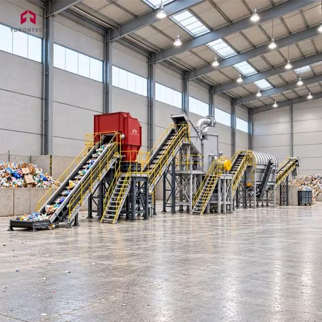
The ToronHazard™ hazardous waste container processing line recovers clean metal and plastic from drums, pails, and industrial packaging that previously held chemicals, solvents, paints, or lubricants. Shredding, crushing, separation, residue removal, sorting, and washing run as one continuous sequence within a single system. Throughput reaches 800 to 5,000 kg/h depending on container type and line configuration. Material leaves the process as washed, saleable feedstock rather than as contaminated waste bound for landfill.
Contaminated packaging places demands on machinery that general recycling equipment does not meet. Cutting chambers absorb impact from partially filled steel drums, and residual solvent or oil has to be released and captured instead of carried through the process. The ToronHazard™ line uses high-strength alloy steel blades selected for wear resistance under steel drum duty, and the structure is built to withstand shock loading. A PLC governs the process sequence, and emergency stop controls sit within operator reach at each machine.
Every installation is configured around the containers arriving at the gate. Infeed dimensions, target throughput, and required output size determine blade geometry, screen selection, and the number of wash stages. Facilities running plastic drums follow a different separation route than those handling steel drums, and mixed streams can run on one line with staged sorting. Reference installations operate between 1,500 and 2,000 kg/h across metal drum, plastic drum, and mixed hazardous waste applications.
Applications
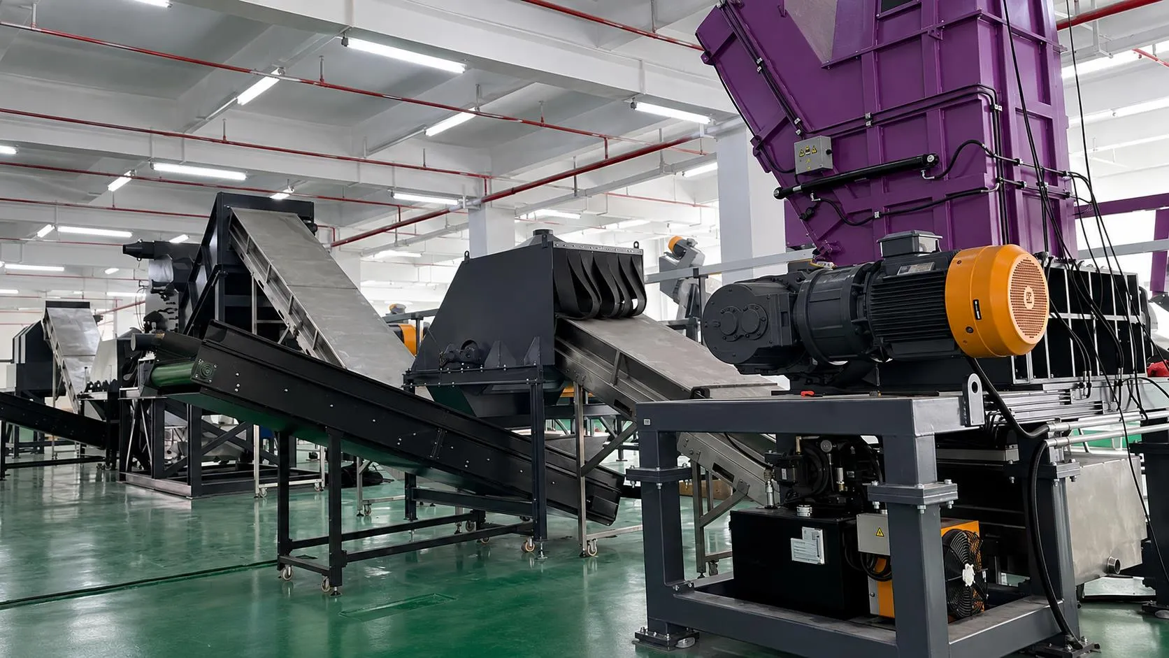
The ToronHazard™ line suits operators who receive contaminated packaging as a waste stream and need to convert it into a clean, marketable material.
- Hazardous Waste Treatment Facilities: processes drums and packaging received from generators, reducing disposal tonnage and creating a recoverable metal and plastic stream
- Chemical Manufacturing: handles solvent, reagent, and additive containers generated on site, keeping empty packaging out of contracted hazardous waste disposal
- Paint, Coatings, and Ink Production: recovers steel and plastic from pails and drums carrying resin, pigment, and solvent residues that resist simple rinsing
- Lubricant and Used Oil Processors: cleans oil drums and pails so the steel can be sold as scrap and residual oil is captured rather than lost to landfill
- Petrochemical and Refinery Operations: treats additive, catalyst, and chemical containers accumulating across refinery maintenance and production units
- Steel Drum Recycling: converts drums unfit for reconditioning into washed steel fragments accepted by mills and scrap buyers
- Plastic Drum and IBC Recycling: separates plastic bodies from metal fittings, cages, and closures for independent recovery of each material
- Agrochemical Packaging Recovery: processes pesticide and fertilizer containers where residue removal determines whether material can be recycled
- Pharmaceutical and Fine Chemical Plants: manages contaminated packaging from production areas under controlled, documented conditions
- Automotive and Heavy Equipment Maintenance: handles bulk lubricant, coolant, and cleaning chemical containers generated by fleet and workshop operations
- Scrap Metal Processors: adds drum decontamination capability so contaminated packaging becomes an accepted rather than rejected input
- Industrial Waste Contractors: provides an on-site or centralized processing route for packaging collected across multiple client sites
Key Features
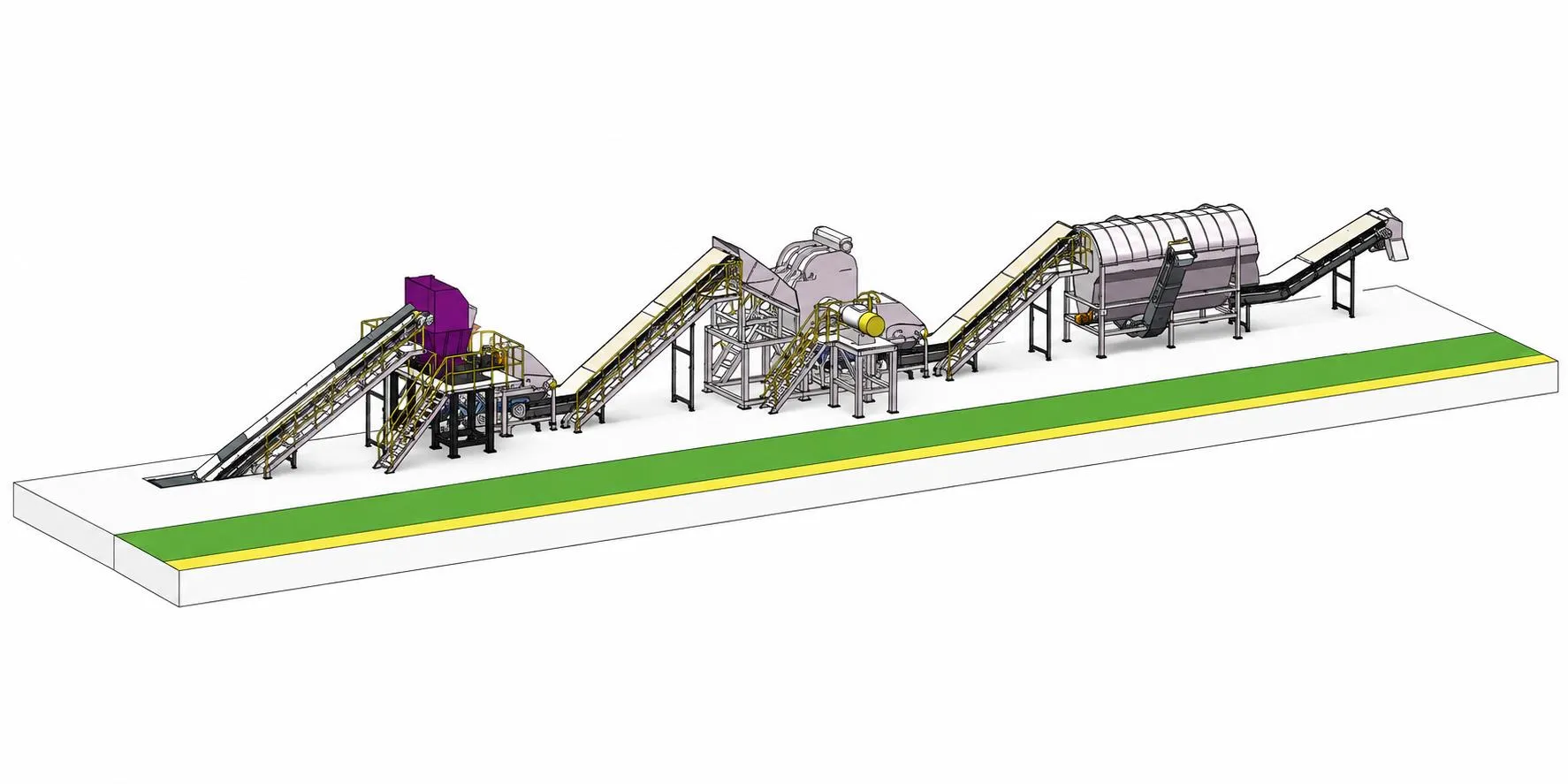
The ToronHazard™ line pairs heavy-duty size reduction with staged washing and separation, and each module is specified against the container type and throughput a site handles.
- Low-Speed High-Torque Twin-Shaft Shredder: counter-rotating shafts shear through steel and plastic drums with quiet operation and without the stalling that high-speed cutters suffer on dense material
- Extended Shredding Dwell Time: material is retained and worked repeatedly inside the cutting chamber, which releases chemical residue and oil trapped in seams and folds
- Multi-Stage Washing: fragments pass through several wash passes so metal leaves the line visibly clean and ready for direct resale
- High-Intensity Magnetic Separation: recovers approximately 99 percent of the ferrous fraction according to supplier data, keeping steel out of the plastic stream
- High-Strength Alloy Steel Blades: cutting tools combine wear resistance with the toughness needed for repeated steel drum duty, extending service intervals
- Impact-Resistant Construction: the machine frame and cutting chamber absorb shock loading from partially filled and deformed containers
- PLC Process Control: one control interface governs the full sequence, simplifying operation and routine maintenance
- Emergency Stop Controls: stop buttons are fitted at the machines so operators can halt the process immediately from the work position
- Integrated Process Sequence: shredding, crushing, separation, residue removal, sorting, and washing operate as a single connected line rather than as standalone units
- Configurable Throughput: capacity is set between 800 and 5,000 kg/h to match site volume and shift pattern
- Application-Specific Engineering: infeed size, output size, and production target drive the equipment selection for each project
- High Material Recovery Rate: separating the shredded stream into distinct fractions raises the share of input converted into saleable output
- Direct-Reuse Output Quality: processed material can go straight to a buyer or move on to further refinement depending on the target market
- Low Noise Operation: slow-turning shafts keep sound levels down compared with high-speed granulating equipment
Theory and Method
Container decontamination starts with breaching the container. A sealed drum protects its residue from any washing medium, so no cleaning step works until the container is opened and reduced. The twin-shaft shredder handles this stage through shear rather than impact: two counter-rotating shafts carry interlocking cutters that grip the drum wall and tear it apart. Low rotational speed combined with high torque lets the machine work through steel without stalling, and it limits the heat and sparking that fast-turning cutters generate around solvent residues.
Dwell time inside the cutting chamber matters as much as cutting force. Material stays between the shafts and is worked repeatedly, which opens seams, folds, and crimped edges where residue collects. Shredding also multiplies exposed surface area, turning a closed vessel into loose fragments with every face accessible. Washing then works on adhesion: contaminants cling to fragment surfaces through surface tension and viscosity, and turbulence plus friction between tumbling fragments breaks that bond. Repeated wash passes lower the residue load progressively.
Magnetic separation exploits the ferromagnetic response of steel. Placed in an applied field, steel fragments develop an induced magnetization, and the resulting attraction force exceeds their own weight, so a high-intensity separator lifts them clear of the stream. Plastic, gasket rubber, label paper, and non-ferrous fittings show no such response and continue along the line. Supplier data reports recovery of approximately 99 percent of the ferrous fraction under this arrangement. Residual non-metallic material is then split by density and particle size to finish the separation.
Technical Specifications
System Overview
| Parameter | Specification |
|---|---|
| System Type | Integrated processing line for contaminated packaging containers |
| Throughput Range | 800 to 5,000 kg/h |
| Reference Installations | 1,500 kg/h (plastic drum line), 2,000 kg/h (metal drum and mixed hazardous waste lines) |
| Process Functions | Shredding, crushing, separation, residue removal, sorting, washing |
| Processable Containers | Steel drums, plastic drums, chemical pails, oil containers, industrial packaging containers |
| Output Streams | Washed ferrous fragments, separated plastic fraction, recovered residue and slag |
| Ferrous Recovery Rate | Approximately 99 percent (supplier stated) |
| Blade Material | High-strength alloy steel |
| Control System | PLC with centralized operator interface |
| Safety Provision | Emergency stop controls fitted at machine positions |
| Structural Rating | Impact-resistant construction for shock loading |
| Output Handling | Direct recycling or further refinement as required |
| Engineering Basis | Configured to infeed size, throughput target, and final output size |
Machine Line-Up
The line is assembled from the modules below. Each stage is described with its function, working method, and available parameters.
1. Feeding System
Containers are charged onto the infeed conveyor by loader, forklift, or manual handling and carried into the shredder at a controlled rate. Steady feeding keeps the shredder inside its torque band and prevents surge loading from a batch of heavy drums.
| Parameter | Specification |
|---|---|
| Function | Meters containers into the primary shredder at a controlled rate |
| Feed Method | Loader, forklift, or manual charging |
| Discharge | Direct into shredder hopper |
| Configuration | Sized to line throughput and container dimensions |
2. Twin-Shaft Shredder
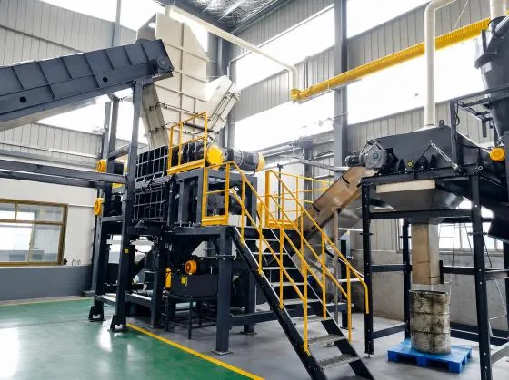 | The twin-shaft shredder performs primary size reduction and opens every container in the stream. Two shafts turn slowly in opposite directions, and interlocking cutters grip the container wall and shear it apart. High torque at low speed carries the machine through steel drum work without stalling, and the slow action keeps noise levels low. Material remains between the shafts long enough to be worked repeatedly, which detaches chemical residue and oil from folds and seams. |
| Parameter | Specification |
|---|---|
| Function | Primary size reduction and opening of sealed containers |
| Rotor Configuration | Twin counter-rotating shafts with interlocking cutters |
| Operating Speed | Low speed |
| Torque Characteristic | High torque across the working range |
| Cutting Action | Shear between opposing cutter sets |
| Blade Material | High-strength alloy steel with high wear resistance |
| Noise Profile | Low noise operation |
| Process Purpose | Releases chemical residue and oil from container surfaces |
| Accepted Input | Steel drums, plastic drums, pails, mixed industrial containers |
3. Secondary Crusher
Shredded fragments pass to a crushing stage that brings material down to the size the downstream separation and washing equipment works best with. Size reduction at this point also breaks apart composite pieces where metal and plastic remain joined, such as closures, clips, and fittings.
| Parameter | Specification |
|---|---|
| Function | Secondary size reduction and liberation of joined materials |
| Position | After primary shredding, ahead of separation and washing |
| Output Size | Set to project requirement during system design |
| Process Purpose | Prepares uniform fragment size for washing and sorting |
4. Washing System
Washing removes the contamination that shredding has exposed. Fragments are flushed multiple times, and turbulence combined with friction between tumbling pieces lifts residue from fragment surfaces. Repeated passes lower the residue load progressively, which is what allows metal fragments to leave the line clean enough for direct sale.
| Parameter | Specification |
|---|---|
| Function | Removal of chemical residue, oil, and adhering contamination |
| Method | Multiple flushing passes with mechanical agitation |
| Cleaning Mechanism | Turbulence and inter-fragment friction breaking surface adhesion |
| Output Condition | Metal fragments cleaned for direct recycling |
| Stage Count | Set to contamination level and output specification |
5. Residue and Slag Removal
Residue lifted during washing, along with settled slag and heavy debris, is drawn off so it does not recirculate into clean material. Removing this fraction at a dedicated point keeps the wash medium working and protects the quality of the finished output.
| Parameter | Specification |
|---|---|
| Function | Extraction of separated residue, slag, and heavy debris |
| Position | Integrated with the washing stage |
| Process Purpose | Prevents recontamination of cleaned material |
| Output | Concentrated residue fraction for controlled disposal or recovery |
6. Magnetic Separation System
A high-intensity magnetic system pulls the ferrous fraction out of the washed stream. Steel fragments magnetize in the applied field and are lifted clear, while plastic, rubber seals, and non-ferrous fittings pass through untouched. Supplier data reports recovery of around 99 percent of the ferrous content.
| Parameter | Specification |
|---|---|
| Function | Recovery of ferrous metal from the washed material stream |
| Field Strength | High-intensity magnetic system |
| Recovery Rate | Approximately 99 percent of ferrous content (supplier stated) |
| Separated Output | Washed steel fragments for direct scrap sale |
| Pass-Through Material | Plastic, rubber, paper, and non-ferrous components |
7. Sorting and Separation
The remaining stream is divided into its component materials. Fragments differ in density, size, and behavior once suspended or agitated, and the sorting stage uses those differences to split plastic from residual non-ferrous pieces and from any remaining debris.
| Parameter | Specification |
|---|---|
| Function | Division of the non-ferrous stream into distinct material fractions |
| Separation Basis | Density and particle size differences between fractions |
| Output Fractions | Plastic fraction, non-ferrous fraction, residual debris |
| Process Purpose | Raises the share of input material converted into saleable output |
| Configuration | Stage selection matched to the container mix on site |
8. Control and Safety System
A PLC coordinates the machines so the line runs as a single process rather than a set of independent units. Operators work from one interface, and emergency stop controls are positioned at the machines so the process can be halted immediately from the work position.
| Parameter | Specification |
|---|---|
| Function | Sequence control, monitoring, and operator safety |
| Controller | PLC with centralized operator interface |
| Operation | Single-point control of the connected process line |
| Safety Devices | Emergency stop buttons fitted at machine positions |
| Maintenance Profile | Simplified operation and routine servicing |