
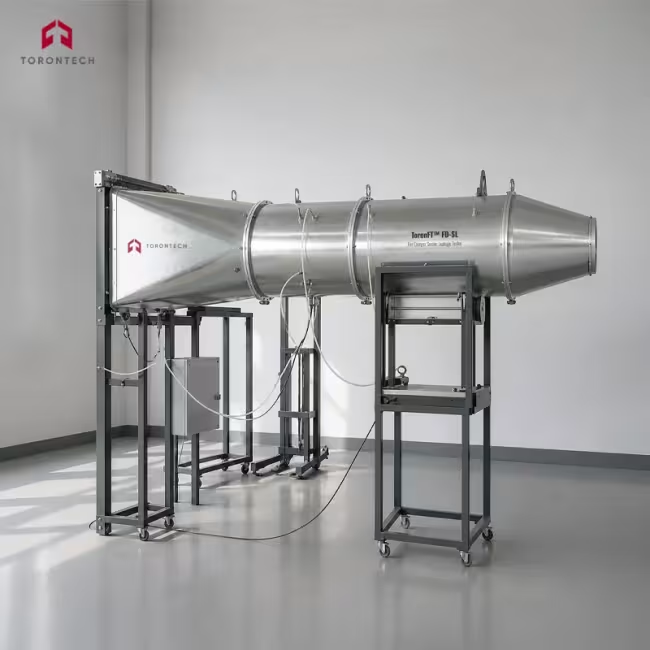
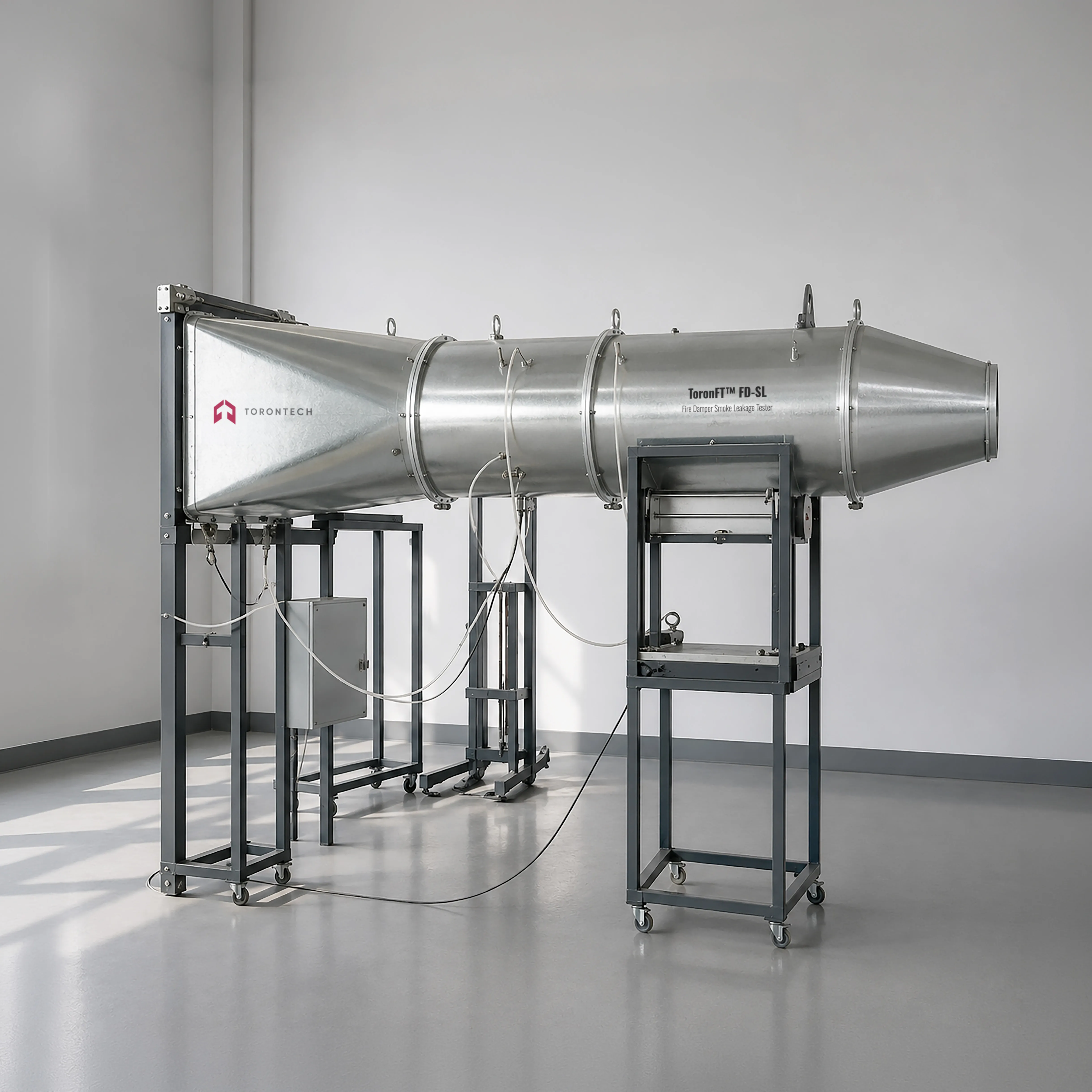
Fire Damper Smoke Leakage Tester
Fire Damper Smoke Leakage Tester - ToronFT™ FD-SL
ToronFT™ FD-SL fire damper smoke leakage tester measures the closed-blade air leakage rate of fire dampers and smoke fire dampers at ambient temperature, providing the quantitative leakage data required for S classification under EN 13501-3 and for compliance verification under EN 1366-2 and EN 1751. The system draws air through a closed damper specimen by means of a VFD-controlled induced-draft fan and measures the resulting volumetric flow rate through a calibrated standard orifice plate, converting the differential pressure across the orifice into leakage flow corrected to a reference temperature of 20°C. Static pressure on the damper face is maintained at either 300 ± 15 Pa or 1000 ± 15 Pa, covering the two principal test conditions specified in the referenced standards.
The instrument accommodates rectangular and circular damper specimens through a set of reducer transition ducts that connect the 300 mm diameter main duct to the outlet face of the damper under test. Standard rectangular reducer ducts in sizes 3.5#, 4#, and 5# are supplied with the instrument; additional reducers for other damper face dimensions are available as options. The main straight test duct is fabricated from 2.0 mm steel plate in a 2 m length at DN300, providing the straight run upstream of the measurement station needed for stable, fully developed flow conditions at the orifice plate. A flow conditioner installed at the entry of the measurement section further eliminates swirl and velocity profile distortion that would otherwise bias the orifice plate reading.
A computer-based data acquisition and control system reads pressure, temperature, and flow signals at six samples per minute, continuously recalculates the corrected leakage rate, and automatically adjusts fan speed through the variable-frequency drive to hold the differential pressure setpoint. The operator selects the target pressure on-screen, the system ramps to setpoint and then logs data for the required measurement period, and the software outputs the corrected leakage in the units and format required by the applicable standard. An atmospheric pressure sensor accounts for altitude and barometric variation, ensuring that flow corrections remain accurate regardless of the laboratory location.
Fire Damper Smoke Leakage Tester - ToronFT™ FD-SL Applications
The ToronFT™ FD-SL is used wherever fire dampers and smoke fire dampers must be tested for closed-blade leakage performance at ambient temperature, either as a standalone qualification test or as part of a pre-fire-test leakage assessment sequence.
- Fire Damper Manufacturers: ambient-temperature leakage qualification testing of new damper designs across the full size range, generating the closed-blade leakage data required for S classification submissions to accredited fire test laboratories and notified bodies.
- Accredited Fire Testing Laboratories: pre-fire-test ambient leakage measurement on the smallest and largest damper sizes per EN 1366-2, confirming that specimens meet the 200 m³/h·m² leakage limit at 300 Pa before proceeding to the furnace fire resistance test.
- HVAC Equipment Certification Bodies: independent leakage measurement for CE marking assessments under EN 15650 (fire dampers) and EN 12101-8 (smoke control dampers), supporting Declaration of Performance documentation.
- Building Services and MEP Contractors: acceptance testing of installed or pre-installation fire dampers to verify that closed-blade leakage meets the specification before the damper is commissioned in a fire compartment boundary.
- Smoke Damper and Fire and Smoke Damper Testing: leakage rate verification of combination fire and smoke dampers at both 300 Pa standard pressure and elevated 1000 Pa system pressure conditions, covering the full range of operational pressure differentials the damper will see in service.
- Quality Assurance in Manufacturing: production-line leakage sampling of finished dampers against a defined leakage acceptance criterion, providing documented evidence of consistency between the tested type and manufactured units.
- Research and Product Development: parametric testing of blade seal geometry, blade tip design, and frame gasket materials during R&D to quantify the contribution of each design variable to leakage performance across a range of pressure differentials.
- Retrofit and Maintenance Verification: post-maintenance leakage checks on fire dampers that have been reopened or resealed following inspection, confirming that seal integrity has been restored before the damper is returned to service.
Standards
The ToronFT™ FD-SL is designed to satisfy the test apparatus, measurement, and procedure requirements of the following international and European standards for fire damper and smoke damper leakage testing at ambient temperature.
- EN 1366-2 - Fire Resistance Tests for Service Installations: Fire Dampers (ambient temperature smoke leakage measurement at 300 Pa prior to and during fire resistance test)
- EN 1751 - Ventilation for Buildings: Air Terminal Devices - Aerodynamic Testing of Dampers and Valves (closed-blade leakage classification and measurement method, pressure differences up to 2000 Pa)
- EN 13501-3 - Fire Classification of Construction Products and Building Elements: Classification Using Data from Fire Resistance Tests on Products and Elements Used in Building Service Installations (S classification based on ambient leakage ≤ 200 m³/h·m² at 300 Pa)
- EN 15650 - Ventilation for Buildings: Fire Dampers (European product standard for fire dampers, referencing EN 1366-2 test method and EN 13501-3 classification)
- EN 12101-8 - Smoke and Heat Control Systems: Smoke Control Dampers (European product standard for smoke control dampers, including leakage classification requirements)
- EN ISO 5167-1 - Measurement of Fluid Flow by Means of Pressure Differential Devices Inserted in Circular Cross-Section Conduits Running Full: General Principles and Requirements (orifice plate flow calculation method referenced by EN 1366-2)
Fire Damper Smoke Leakage Tester - ToronFT™ FD-SL Key Features
The ToronFT™ FD-SL integrates a calibrated orifice plate flow measurement train, a VFD-controlled inducer fan, and computer-based closed-loop pressure control in a compact duct assembly purpose-built for ambient-temperature fire damper leakage testing.
- Dual Pressure Setpoints at 300 Pa and 1000 Pa: the control system targets either 300 ± 15 Pa for the standard EN 1366-2 and EN 1751 leakage test or 1000 ± 15 Pa for higher-pressure smoke damper tests, selectable from the operator interface without any hardware change.
- Standard Orifice Plate with Micro-Differential Pressure Measurement: a calibrated orifice plate to EN ISO 5167-1 in the DN300 test duct provides traceable, repeatable flow measurement; a high-accuracy micro-differential pressure transducer captures the orifice pressure drop with the resolution needed for low-leakage dampers.
- VFD-Controlled 5 kW Induced-Draft Fan with Closed-Loop Pressure Control: a frequency inverter continuously adjusts fan speed to maintain the pressure differential across the closed damper at the setpoint, eliminating the manual rebalancing needed with fixed-speed fan systems and holding pressure within the required tolerance band throughout the measurement period.
- DN300 Straight Steel Test Duct with Flow Conditioner: 2.0 mm welded steel duct in a 2 m straight length provides the developed flow profile needed for accurate orifice plate reading; a gas-flow conditioner at the duct inlet removes swirl and profile distortion from the incoming air stream.
- Rectangular and Circular Reducer Transition Ducts: standard reducer sets in sizes 3.5#, 4#, and 5# connect the DN300 test duct to rectangular damper outlets of matching face dimensions; a circular reducer adapts round dampers to the same duct; additional reducer sizes are available to order.
- Flexible Duct Connection Between Fan and Test Section: a flexible coupling isolates fan vibration from the measurement duct, preventing mechanical vibration from disturbing the micro-differential pressure readings at the orifice and pressure transducers.
- Integrated Atmospheric Pressure Sensor: a barometric pressure sensor compensates flow calculations for variations in site altitude and weather, so leakage results corrected to 20°C and standard atmosphere are accurate regardless of where the laboratory is located.
- Three-Channel Sensor Suite at 1500 mm from Damper Face: pressure, temperature, and atmospheric sensors are all installed at the 1500 mm measurement plane specified by the standard, keeping all data collection at the correct location relative to the damper specimen.
- Computer-Controlled Data Acquisition at 6 Samples per Minute: the acquisition system records all channels six times per minute, applies the EN ISO 5167-1 orifice flow formula and the temperature-pressure density correction in real time, and displays the current corrected leakage rate on-screen continuously during the test.
- Automatic Leakage Calculation and Report Output: the software computes corrected leakage rate from measured pressure, temperature, and orifice differential pressure, checks stability against the required tolerance criterion, and outputs the test result in m³/(h·m²) ready for comparison with the S classification acceptance limit.
Theory and Method
Smoke leakage through a closed fire damper is driven by the static pressure difference between the duct on the pressurised side of the damper and the ambient laboratory air on the outlet side. At ambient temperature, this leakage consists entirely of air passing through gaps at blade tips, blade-to-frame interfaces, and frame-to-duct penetrations. Measuring this air flow rate under a defined and controlled pressure differential produces a leakage coefficient that the standards use to predict how much smoke would pass through the closed damper during a fire event. The ToronFT™ FD-SL applies the target under-pressure on the outlet side of the specimen by drawing air out of the connected duct with an induced-draft fan, so that the pressure difference across the closed damper blades equals the specified setpoint of 300 Pa or 1000 Pa relative to the surrounding laboratory atmosphere.
Flow rate through the closed damper is measured by a standard orifice plate installed in the straight 2 m test duct upstream of the fan. The orifice plate creates a differential pressure between the upstream tapping and the vena contracta downstream, and the Bernoulli equation for incompressible flow gives a volumetric flow rate proportional to the square root of that differential pressure, with discharge coefficients and expansibility factors defined in EN ISO 5167-1. A high-accuracy micro-differential pressure transducer measures the orifice pressure drop, and the software applies the full EN ISO 5167-1 correction to convert it to a volumetric flow rate. A temperature sensor 1500 mm downstream of the damper face and an atmospheric pressure sensor together provide the air density value used to correct the measured volumetric flow to the reference condition of 20°C and standard atmospheric pressure, as required by EN 1366-2 when reporting results for S classification.
Pressure stability across the damper face is maintained by the variable-frequency drive controlling the inducer fan speed in a closed-loop with the static pressure signal from the transducer mounted 1500 mm from the damper. The VFD responds to deviations from the setpoint by adjusting fan speed until the pressure recovers within the ±15 Pa tolerance band. The data acquisition system samples all channels six times per minute and monitors the stability criterion: readings are considered stable when successive measurements agree within ±5% over a defined window, consistent with the recording interval requirement in EN 1366-2. The leakage result is calculated from the mean of stable readings, corrected to 20°C, and expressed as a leakage rate per unit of damper face area in m³/(h·m²) for direct comparison with the S classification threshold of 200 m³/(h·m²).
Fire Damper Smoke Leakage Tester - ToronFT™ FD-SL Technical Specifications
| Parameter | Specification |
|---|---|
| Product Name | Fire Damper Smoke Leakage Tester at Normal Temperature |
| Model | ToronFT™ FD-SL |
| Applicable Standards | EN 1366-2, EN 1751, EN 13501-3, EN 15650, EN 12101-8, EN ISO 5167-1 |
| Test Application | Closed-blade smoke leakage measurement of fire dampers and smoke fire dampers at ambient (normal) temperature |
| Specimen Types | Rectangular fire dampers and circular fire dampers; fire and smoke combination dampers |
| Test Pressure Setpoint 1 | 300 ± 15 Pa (standard EN 1366-2 / EN 1751 leakage test pressure) |
| Test Pressure Setpoint 2 | 1000 ± 15 Pa (elevated pressure test per applicable standard) |
| Pressure Control Method | Closed-loop VFD control of induced-draft fan; automatic setpoint tracking |
| S Classification Acceptance Limit | ≤ 200 m³/(h·m²) at 300 Pa corrected to 20°C per EN 13501-3 / EN 1366-2 |
| System Composition | Gas flow measurement system (duct, orifice plate, micro-differential transducer, flow conditioner) and pressure measurement and control system (VFD fan, static pressure transducer, control computer) |
| Main Test Duct | DN300, round; 2.0 mm welded steel plate; 2 m straight length |
| Transition (Reducer) Ducts – Rectangular | Standard sizes: 3.5#, 4#, 5# rectangular-to-DN300 reducers; outlet width and height match corresponding rectangular damper outlet dimensions |
| Transition (Reducer) Ducts – Circular | Circular-to-DN300 reducer; outlet diameter matches circular damper outlet |
| Flow Measurement Device | Standard orifice plate to EN ISO 5167-1; micro-differential pressure gauge reads orifice ΔP |
| Flow Conditioner | Gas flow conditioner installed at duct inlet to eliminate swirl and velocity profile distortion |
| Induced-Draft Fan Power | 5 kW |
| Fan Inlet Valve | DN300 inlet isolation valve |
| Fan Speed Control | Variable-frequency drive (VFD); adjusts airflow and pressure continuously |
| Fan-to-Duct Connection | Flexible duct coupling isolates fan vibration from measurement section |
| Pressure Sensor | Pressure transducer; measurement range 100 to 1500 Pa |
| Temperature Sensor | Temperature sensor; measurement range 0 to 100°C |
| Atmospheric Pressure Sensor | Barometric pressure sensor; compensates flow calculation for altitude and weather variation |
| Sensor Installation Position | 1500 mm downstream from damper face |
| Pressure Measurement Accuracy | ±3 Pa |
| Temperature Measurement Accuracy | ±2.5°C |
| Flow Measurement Accuracy | ±2.5% |
| Data Acquisition Rate | 6 readings per minute (one reading every 10 s) |
| Control System | Computer with data acquisition card; real-time data capture, automated pressure control, automatic leakage calculation corrected to 20°C |
| Leakage Calculation Method | Orifice plate differential pressure converted to volumetric flow per EN ISO 5167-1; corrected to 20°C and standard atmospheric pressure using measured temperature and barometric pressure; expressed as m³/(h·m²) |
| Stability Criterion | Readings accepted when successive measurements stabilise within ±5% over the required recording interval, consistent with EN 1366-2 requirements |
Standard Configuration
| Item | Description |
|---|---|
| Main Test Duct Assembly | DN300, 2.0 mm welded steel, 2 m straight run with orifice plate, flow conditioner, and sensor tapping ports |
| Rectangular Reducer Transition Ducts | 3.5#, 4#, and 5# rectangular-to-round reducers; mates rectangular damper outlet to DN300 test duct |
| Circular Reducer Transition Duct | Circular-to-DN300 reducer for round damper specimens |
| Induced-Draft Fan System | 5 kW inducer fan, DN300 inlet valve, VFD speed controller, flexible duct coupling |
| Flow Measurement System | Standard orifice plate (EN ISO 5167-1), micro-differential pressure gauge, gas flow conditioner |
| Pressure and Temperature Sensor Assembly | Pressure transducer (100–1500 Pa), temperature sensor (0–100°C), barometric pressure sensor; all at 1500 mm measurement position |
| Computer Control and Data Acquisition System | PC workstation with acquisition card; closed-loop pressure control software; real-time leakage display; automatic test report output |