
Circuit Integrity Tester
Circuit Integrity Tester - ToronFT™ CIT
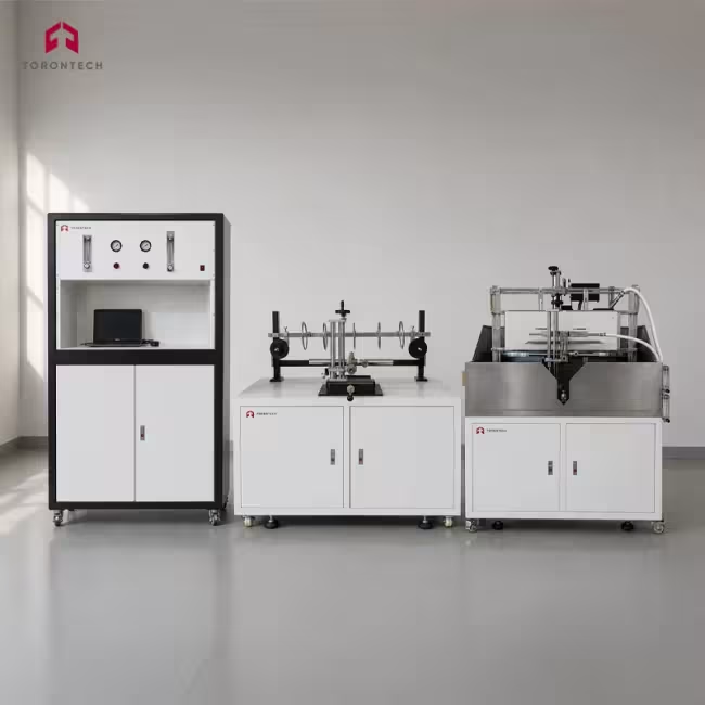
ToronFT™ CIT wire cable circuit integrity flame tester evaluates whether electric cables and optical fibre cables can maintain circuit continuity when exposed to a controlled propane flame at temperatures of at least 750°C or 830°C. It serves cable manufacturers, testing laboratories, and quality assurance engineers who need to qualify fire-resistant cable products against international standards. The system applies heat directly to a horizontally mounted cable sample while live voltage runs through the conductors, confirming that no short circuit or open circuit occurs during or after the flame exposure period.
The ToronFT™ CIT handles both fire-alone tests and fire-with-shock tests, covering a wide range of cable types including low-voltage power cables, data cables, and optical fibre cables. The ribbon-type propane burner delivers a 500 mm flame zone across the sample, and a Venturi gas mixing system maintains a stable, reproducible flame throughout the test. Two K-type mineral-insulated thermocouples continuously measure flame temperature, and a built-in verification timer ensures the heat source meets the calibration criteria specified in IEC 60331-11 before testing begins.
A PC-based control interface manages the complete test sequence, from automated ignition through flame shutoff and post-fire continuity monitoring. An isolation transformer supplies the test voltage to each cable conductor at up to 1000 V (phase voltage), with a 2 A fuse on every conductor circuit that trips automatically if the sample loses circuit integrity. The control cabinet integrates overcurrent, short-circuit, and gas supply shutdown safety circuits, making the ToronFT™ CIT suitable for independent test laboratories and in-house production verification facilities operating under strict safety protocols.
Circuit Integrity Tester - ToronFT™ CIT Applications
The ToronFT™ CIT covers the full scope of cable circuit integrity testing across power, data, and optical fibre cable types. It is used wherever fire-resistant cables must be qualified for safety-critical circuits that must remain operational during a fire event.
- Fire-Resistant Power Cable Manufacturing: type tests and batch acceptance testing of armoured and mineral-insulated cables rated at 0.6/1 kV and below, verifying compliance before product release.
- Independent Testing Laboratories: third-party circuit integrity qualification testing for cable manufacturers seeking IEC 60331, BS 6387, or EN 50200 compliance certification.
- Emergency Systems Infrastructure: testing cables intended for fire alarms, emergency lighting, smoke control fans, and sprinkler pump circuits that must function throughout a fire.
- Building and Construction Projects: qualification of cables specified under fire-safety codes requiring circuit integrity for evacuation and suppression systems in high-rise and public buildings.
- Data and Telecommunications Cable Verification: fire integrity testing of data cables per IEC 60331-23, confirming signal circuit continuity under 750°C flame exposure.
- Optical Fibre Cable Testing: continuity pass/fail assessment of optical fibre cables under IEC 60331-25, determining whether light transmission survives a prescribed fire exposure.
- Industrial and Offshore Facilities: qualification of cables routed through hazardous areas where fire events demand sustained circuit operation for safety shutdowns and process control.
- Cable Conduit System Testing: evaluation of low-voltage cables installed inside metal conduit under fire and mechanical shock conditions per IEC 60331-11.
Standards
The ToronFT™ CIT is designed to satisfy the test apparatus and procedural requirements of the IEC 60331 series and related international fire integrity standards for cables and optical fibre cables.
- IEC 60331-11 - Tests for Electric Cables Under Fire Conditions: Circuit Integrity - Apparatus, Fire Alone at Flame Temperature Minimum 750 °C
- IEC 60331-21 - Tests for Electric Cables Under Fire Conditions: Circuit Integrity - Procedures and Requirements, Cables of Rated Voltage Up to and Including 0.6/1.0 kV
- IEC 60331-23 - Tests for Electric Cables Under Fire Conditions: Circuit Integrity - Procedures and Requirements, Electric Data Cables
- IEC 60331-25 - Tests for Electric Cables Under Fire Conditions: Circuit Integrity - Procedures and Requirements, Optical Fibre Cables
Circuit Integrity Tester - ToronFT™ CIT Key Features
The ToronFT™ CIT combines dual-mode flame test capability, precision gas metering, and PC-based automation in a single system designed for professional test laboratory use.
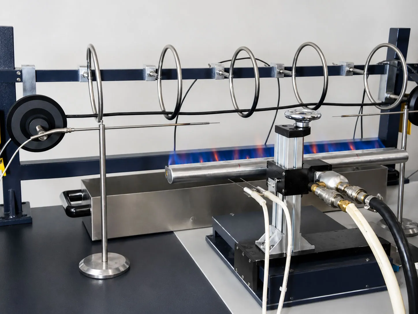
- Dual-Mode Test Configuration: ships with both fire-alone and fire-with-shock test bench assemblies, covering IEC 60331-11 and IEC 60331-1/2/3 without requiring additional hardware purchases.
- Precision Mass Flow Metering: separate mass flow controllers for propane and compressed air deliver tightly regulated gas ratios, keeping flame temperature stable throughout the full test duration.
- Two-Thermocouple Flame Verification System: paired K-type mineral-insulated thermocouples measure flame temperature at calibrated positions and verify the burner output against IEC 60331-11 acceptance criteria before any cable test begins.
- 750°C to 1000°C Adjustable Flame Temperature: a wide temperature range accommodates fire-alone tests at the 750°C baseline and fire-with-shock tests at 830°C, with margin for higher-temperature research applications.
- 0 to 1000 V Continuously Adjustable Test Voltage: a three-phase star-connected isolation transformer with variable output covers the rated voltage of all cable types addressed by the IEC 60331 series, from low-voltage power cables to data cables.
- Per-Conductor 2 A Fuse Circuit: each conductor or conductor group connects through an independent 2 A fuse, so the exact moment of circuit failure is captured individually for each conductor rather than as a combined indication.
- Automated Ignition, Timing, and Shutdown: a pilot flame igniter starts the burner automatically, and the PC control system runs the full test sequence including timed flame application up to 999 minutes and automatic gas shutoff on completion or fault detection.
- Optical Fibre Continuity Support: the test bench accommodates optical fibre cable samples per IEC 60331-25, with provisions for connecting customer-supplied optical instruments to monitor light transmission continuity during the test.
- Integrated Safety Interlock System: power overload protection, short-circuit protection, control circuit overload, and automatic gas supply cutoff on circuit failure or flame extinction operate as standard, with audible and visual alarm indication.
- PC-Based Control and Data Interface: a laptop PC communicates with the instrument over a USB-to-RS485 link, displaying live thermocouple readings, test status, and timer data, with records storable for test report generation.
Theory and Method
Circuit integrity testing determines whether a cable can sustain uninterrupted electrical or optical transmission for a defined period while a controlled flame attacks the cable's insulation and jacket. The test simulates the thermal environment of a structural fire by applying a propane-fuelled ribbon burner directly beneath the cable sample. The propane and compressed air combine through a Venturi mixer, producing a stable, uniform flame across a 500 mm burner face. As the cable surface temperature rises, the insulation degrades and chars, but a properly designed fire-resistant cable contains mineral or mica-based fire barriers that preserve the conductor separation and prevent short circuits or open circuits from developing.
Two K-type thermocouple probes, each 1.5 mm in diameter with a mineral-insulated stainless steel sheath, measure the actual flame temperature at defined positions relative to the burner face. The average of both readings over a 10-minute verification run must fall within the specified temperature tolerance band, such as 750 °C ± 50 °C for fire-alone tests or 830 °C ± 40 °C for fire-with-shock tests, and the difference between the two readings must not exceed 40 °C. This two-thermocouple verification requirement eliminates the possibility that a localised temperature deviation passes undetected, giving confidence that every test run begins with a verified, consistent heat source.
Throughout the flame exposure, live test voltage from an isolation transformer flows through each conductor or conductor group in the cable sample. A 2 A fuse protects each conductor circuit, and if the fuse opens, the control system records a circuit failure and shuts down the gas supply and test voltage. For the fire-with-shock configuration, the cable mounts on a vertical non-combustible board measuring 900 mm by 300 mm, which a mechanical hammer strikes repeatedly at defined intervals to simulate the physical impact of falling debris during a fire. This combined thermal and mechanical loading represents the most demanding in-service condition for fire-circuit cables, matching the scenario described in IEC 60331-1, IEC 60331-2, and IEC 60331-3 for cables of rated voltage 0.6/1 kV and below.
Circuit Integrity Tester - ToronFT™ CIT Technical Specifications
| Parameter | Specification |
|---|---|
| Product Name | Circuit Integrity Tester |
| Model | ToronFT™ CIT |
| Applicable Standards | IEC 60331-1, IEC 60331-2, IEC 60331-3, IEC 60331-11, IEC 60331-21, IEC 60331-23, IEC 60331-25 |
| Test Modes | Fire alone (no shock); Fire with mechanical shock and impact |
| Applicable Cable Types | Electric cables and optical fibre cables, rated voltage 0.6/1 kV and below |
| Flame Temperature Range | 750°C to 1000°C, adjustable |
| Fire-Alone Verification Temperature | 750°C ± 50°C (IEC 60331-11) |
| Fire-with-Shock Verification Temperature | 830°C ± 40°C |
| Max Thermocouple Spread | ≤40°C between two measurement thermocouples during verification |
| Burner Type | Ribbon-type propane gas burner with Venturi air-gas mixer |
| Burner Flame Face Length | 500 mm (nominal) |
| Burner Flame Face Width | 15 mm (nominal) |
| Burner Hole Diameter | 1.32 mm (nominal), 3.2 mm centre-to-centre, three staggered rows |
| Combustion Gas | Propane, minimum 98% purity (customer supplied) |
| Combustion Support Gas | Compressed air, minimum 0.8 MPa supply pressure (customer supplied) |
| Air Mass Flow Rate | 3270 ± 163 mg/s |
| Propane Mass Flow Rate | 320 ± 13 mg/s |
| Ignition System | High-voltage automatic spark igniter with continuous pilot flame |
| Temperature Measurement | Two K-type thermocouples, 1.5 mm diameter, mineral-insulated stainless steel sheath |
| Thermocouple Position (Fire Alone) | Burner horizontal distance approx. 45 mm (x), vertically below thermocouple centreline 70 mm (y) |
| Thermocouple Position (Fire with Shock) | Thermocouple tip 20 ± 1 mm from test wall front face, 100 mm above test wall base; burner horizontal distance 100–120 mm, vertically below 40–60 mm |
| Verification Timer | 0 to 99.99 min, auto stop at set point, accuracy ±1 s/h |
| Flame Application Time (Test) | 0 to 999 min, adjustable |
| Sample Support (Fire Alone) | 3 cable support rings, internal diameter approx. 150 mm, fabricated from 10 ± 2 mm round steel bar; one end fixed, one end free to allow thermal expansion |
| Sample Support (Fire with Shock) | Vertical non-combustible board, 900 mm × 300 mm × 9 mm, with mechanical hammer impact system |
| Circuit Integrity Test Voltage | 0 to 1000 V (phase voltage), continuously adjustable |
| Test Voltage Source | Three-phase star-connected isolation transformer, 8 kVA, 3-phase 400 V input; output neutral-to-line 600 V, phase-to-phase approx. 1200 V; output current 2.5 A |
| Voltage Adjustment | Contact voltage regulator, 3-phase 380 V input, 0–450 V output, 10 kVA |
| Per-Conductor Test Current | 0.25 A |
| Circuit Failure Fuse | 2 A, Type D II |
| Voltage | 3-phase 5-wire, 380 V ±10%, 50 Hz |
| Running Power Consumption | 1 kW (instrument); 6 kW (total system including transformer) |
| Control Interface | PC (laptop) with USB-to-RS485 adapter; IO module with 8 digital inputs and 8 relay outputs |
| Combustion Chamber | 27 m³ ventilated burn chamber (customer supplied or purchased separately) |
| Exhaust Duct Diameter | 360 mm; (ducted to exterior, customer installed) |
| Operating Temperature | 5°C to 30°C |
| Storage Temperature | 0°C to 45°C (impact/shock assembly stored outside burn chamber) |
| Operating Atmospheric Pressure | 86 to 106 kPa |
Standard Configuration
| Item | Description |
|---|---|
| Main Unit | 1 unit, includes control cabinet, gas control system, and safety interlocks |
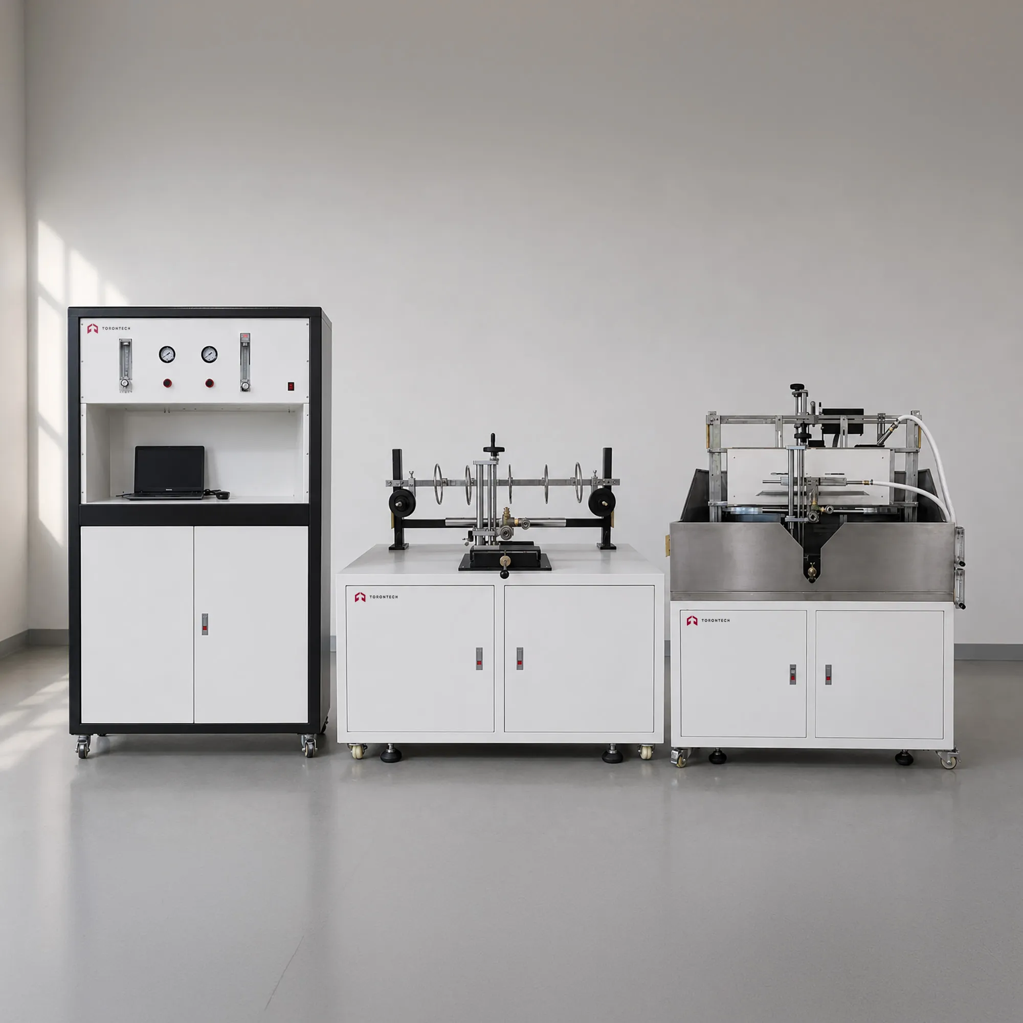
| Fire-Alone Test Apparatus | 1 set, per IEC 60331-11: horizontal cable support frame with 3 wire support rings, internal diameter approx. 150 mm |
| Fire-with-Shock Test Apparatus | 1 set, per IEC 60331-1/2/3: vertical test wall with mechanical hammer impact system |
| Flame Verification Device | 1 set, two K-type mineral-insulated thermocouples with positioning fixtures for IEC 60331-11 and IEC 60331-1/2/3 verification |
| High Voltage and Gas Safety Package | Included: electromagnetic shutoff valves, pressure gauges, pressure regulators, overcurrent and short-circuit protection |
Customer-Supplied Items
| Item | Requirement |
|---|---|
| Propane Gas | Minimum 98% purity |
| Compressed Air Supply | Minimum 0.8 MPa supply pressure |
| Electrical Supply | 3-phase 5-wire, 380 V ±10%, 50 Hz; dedicated circuit, breaker required |
| Combustion Chamber | 27 m³ ventilated burn chamber |
| Exhaust Ducting | 360 mm diameter duct to exterior |
| Optical Instrument (optional) | For optical fibre continuity monitoring per IEC 60331-25 (customer connects to test bench) |