Pro Tips: Spark OES Sample Preparation Guide
An advanced spectrometer cannot compensate for a poorly prepared metal sample. Many material testing labs unknowingly compromise their elemental analysis before the spark sequence even begins, leading to inconsistent, skewed data. While direct solid analysis avoids wet-chemistry contamination, sample condition strongly dictates final result stability.
This guide outlines the essential preparation steps to establish a flat, spark-stable surface that keeps your chemical numbers highly accurate.
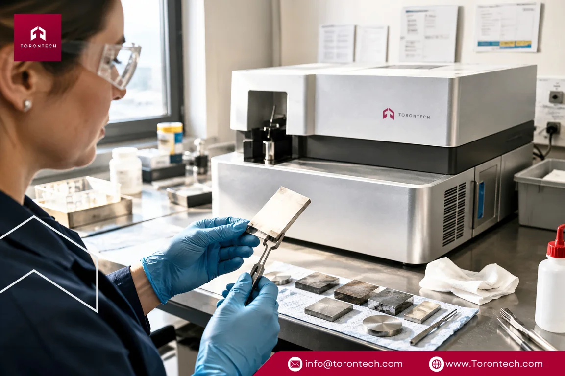
| Metal Category (Matrix) | Recommended Surfacing Tool | Primary B2B Operational Benefit |
|---|---|---|
| Hard Alloys (Steel, Iron, Nickel, Titanium) | Abrasive Grinding (40–80 Grit Disc) | Yields a highly flat, scratch-patterned surface for a stable discharge. |
| Soft Alloys (Aluminum, Copper, Zinc, Lead) | Milling Machine or Lathe | Shears the top layer cleanly, preventing metal smearing and grit contamination. |
Why Surface Preparation Dictates OES Accuracy
Why is this step so critical to your operational success? Let's break down the essential mechanics:
The Leak-Proof Argon Seal
The spark stand must form a snug, airtight seal against the metal surface. Operating in ambient air introduces interfering oxygen and nitrogen lines, whereas enclosing the electrodes and using argon gas dramatically improves high-precision analysis.
If your sample has even a minor surface deviation, air will leak in. This oxygen absorbs the critical light wavelengths needed to detect elements like Carbon or Sulfur. For advanced hardware like the TT-OES9000, which operates in an auto-controlled vacuum within 6–15 Pa to capture the 130nm to 800nm range, a proper seal is vital.
Representative Surface Chemistry
The prepped surface must look exactly like the internal structure of the metal block. Surface defects or localized variations can cause massive position-to-position intensity changes due to poor sampling efficiency.
For demanding checks, such as analyzing ultra-low carbon and nitrogen in steel, proper sample preparation conditions are a mandatory part of the core testing protocol.
Related article: PMT vs CCD: Spark Spectrometry Detector Comparison
Standard Operating Procedures for Sample Surfacing
Let’s walk through the actual steps a lab technician should follow, starting from the very beginning.
1. Ensure Operator Safety and Dust Extraction
We believe a safe workspace is the starting point for reliable data. Grinding industrial alloys releases fine metallic particles into the air, which pose health risks to your operators.
For North American laboratories, meeting OSHA regulations in the US or CCOHS guidelines in Canada regarding hazardous metallic dust exposure and combustible metal particles is a critical compliance issue. In our view, turning on a heavy-duty exhaust system with high-efficiency particulate filtration is a necessary first step before starting any physical prep work.
2. Control Sample Temperature During Cutting
Before you can polish the surface, you must cut the sample to fit the spark stand. When separating a test piece from a larger casting, we consider ample liquid coolant to be a strict requirement. Allowing the metal to get excessively hot changes its metallurgical structure, which ruins the test before it even begins.
3. Select Surfacing Method Based on Material Hardness
Routine metallic samples are often prepared by making one side smooth and bright before measurement. Interestingly, one commercial alloy comparison study utilized flat-cut, unpolished cylindrical blocks to match real test surfaces, showing that polishing is not always mandatory if calibration and sample state are aligned perfectly.
However, we frequently notice a tendency to use a single preparation tool for all materials to save time. Your choice of tool must depend entirely on the physical hardness of the metal:
- For Hard Alloys (Fe, Ni, Ti bases, and Cast Iron): Go with abrasive grinding. A heavy-duty rotary disc grinder or a fast belt sander with 40 to 80 grit works very well to produce a flat, clean surface for a stable spark discharge.
- For Soft Alloys (Al, Cu, Zn, Pb bases): Grinding wheels will smear the soft metal and trap abrasive grit within the sample. For these materials, we believe shaving the surface with a milling machine or lathe is the only reliable way to get a clean, flat face.
(To support this, Torontech provides a complete line of cost-effective sample preparation machines, including industrial-grade disc grinders and milling machines, so your laboratory has the right equipment for every metal matrix.)
4. Prevent Cross-Contamination
In our view, preventing cross-contamination requires strict laboratory discipline. Never use a grinding belt that was just used on copper to prep a piece of steel.
Those copper particles will transfer to the steel surface, and your spectrometer will report trace copper that does not exist in the melt. We suggest using dedicated grinding belts for distinct metal types.
Furthermore, operators must never touch the prepared analytical surface with bare hands. Human skin transfers natural oils and moisture, introducing hydrocarbons that immediately cause false carbon and hydrogen spikes during the spark sequence.
5. Minimize Post-Prep Exposure to Avoid Oxidation
We suggest treating elapsed time as an active variable the moment you finish polishing. Freshly prepped metal surfaces begin oxidizing immediately when exposed to ambient air.
That micro-layer of oxidation acts as an electrical insulator, disrupting the spark. We recommend placing your sample on the spectrometer immediately after surfacing it.
6. Standardize Preparation of Calibration Blocks
We think neglecting the preparation of standard blocks is a common mistake that many laboratory managers make. When adhering to strict North American testing protocols, such as ASTM E415 for carbon and low-alloy steel or ASTM E1251 for aluminum alloys, sample consistency is highly regulated.
Whether you are running your daily standardization checks with setting-up samples (SUS) or verifying accuracy with certified reference materials (CRMs), you must prep them using the exact same methods as your production samples. Inconsistent preparation leads to systematic calibration drift.
7. Optimize Argon Purity and System Purging
Argon flushing is part of a practical measurement setup in prepared metal samples. In our opinion, purchasing low-grade gas is a false economy. One thin-sample study successfully used argon purity greater than 99.995% with a two-second flush before discharge.
For optimal results on modern equipment like the TT-OES9000, we suggest using 99.999% purity Argon at a pressure of >4MPa, which consumes about 5L/min during the actual spark mode. Additionally, electrode and holder design are also part of effective preparation because electrode material contributes spectral lines and the sample must sit in the discharge region reproducibly.
Discharge behavior also depends on electrode material, gap, voltage, and gas flow, meaning preparation extends beyond surface finishing to the full sampling geometry.
Related article: Comparing Spark OES vs ICP OES for Your Laboratory
Preparation for Nonstandard and Small Samples
Testing small fasteners, thin wires, molten metals, or uniquely shaped scrap pieces requires extra preparation. If a piece of thin stainless steel is under three millimeters thick, it will overheat, lose stability, and break down. If the piece is too small, it will not seal the spark stand aperture.
We believe you shouldn't have to build complex, in-house fixtures to solve this. Instead, consider these approaches based on specialized material studies:
- For thin stainless steel or sheet metal: Use an auxiliary thickening device or clamp a thick copper backing support to the sample to act as a heat sink.
- For small solid samples: Press the sample (even weights around 0.7 grams of solid) into holes in a copper support disk to enable point-to-plane analysis without major interference. Alternatively, hardware like the TT-OES9000 features a customized small sample clamp suitable for routine analysis of pieces with diameters ranging from 1mm to 8mm.
- For molten aluminum and alloys: Produce a chill-cast disk directly from the liquid metal to create a form suitable for quantitative spark emission testing.
- For nonstandard testing electrodes: Prepare pieces with a common matrix or internal standard, which reduces anomalous spark effects and improves precision.
Evaluating Prep Quality: Analyzing Burn Spots
In our view, visually inspecting the burn spot after the spark sequence is one of the simplest, most practical habits a laboratory can establish. We believe it saves hours of troubleshooting when analytical results look unexpected.
- The Good Burn: A successful analysis leaves a concentrated, dark spot surrounded by a clean, light-colored ring. This indicates a stable spark and an effective gas seal. The chemical reading is satisfyingly spot on: highly accurate but without requiring endless manual calibrations. The analyzed sample is completely clean from surface to core, and the final spectral output is sheer proof of quality.
- The Bad Burn: If the spot looks milky, sooty, highly irregular, or shows signs that the spark wandered across the surface, your prep or your seal was inadequate. If you see this, resurface the sample and run the test again.
Analytical Limitations and Advanced Variants
Standard spark-OES preparation is simplest for conductive solids. We acknowledge that standard methods have limited suitability for nonconductive materials and poor spatial resolution.
However, variations exist: sliding spark spectrometry allows direct in-situ analysis of compact non-conductive material without prior sample preparation, and LA-SD-OES uses a laser to localize the spark to an ablated spot for advanced imaging.
Related article: LIBS vs OES: Comparative Guide for Material Testing
Optimizing Your Workflow with Torontech
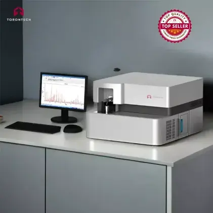
At Torontech, we have developed our instrumentation based on these everyday laboratory realities. Our TT-OES9000 OES Optical Emission Spectrometer was built because we know that busy labs must balance strict quality requirements with quick turnaround times.
- Optimized Spark Stand: We built our spark stand to be argon flushed with minimal maintenance and minimal consumption. It includes spray discharge electrode technology and the aforementioned small sample clamp so you do not have to struggle with irregular shapes.
- High-Accuracy Optics: Featuring high-resolution detectors and a Paschen-Runge layout utilizing a Rowland Circle of Diameter 400mm, it reads up to 31 different elements at the exact same time.
- Efficient Data Processing: Operating on a familiar Microsoft Windows 7 interface, the TT-OES9000 relies on its HEPS digital excitation source and DM9000A Ethernet transmission hardware to process spectrum data five times faster than legacy systems.
- Modular Design: Depending on your facility footprint, it is available as a space-efficient bench-top model weighing 80Kg or a full floor module at 120Kg.
Note: If you need to verify chemistry out on the receiving dock or scrap yard, we also offer the ToronOES™ M, a portable mobile spark optical emission spectrometer you can bring directly to the material. This is particularly useful in North American recycling yards when sorting scrap to meet Recycled Materials Association (ReMA, formerly ISRI) specifications.
Trust Torontech for Reliable Metal Analysis
Establishing correct sample prep methods is the most reliable way to prevent material non-conformance and pass your quality audits. We believe premium testing accuracy shouldn't carry an over-inflated price tag. At Torontech, our focus is on providing cost-effective solutions and innovative technologies that solve your daily laboratory challenges and keep your quality control running smoothly.
Contact a Torontech specialist today to configure the ideal testing setup for your facility, and let’s get your quality control running the right way.
References (Click to expand)
- ASTM. (2021). Practices for Sampling and Sample Preparation of Aluminum and Aluminum Alloys for Determination of Chemical Composition by Spark Atomic Emission Spectrometry. ASTM International.
- Catlett, C., Rollins, M., Griffin, E. B., & Dorsey, J. (1977). Sample preparations for spark source mass spectrography. Y-12 National Security Complex.
- Golloch, A., & Seidel, T. (1994). Sliding spark spectroscopy — a new excitation source for generating atomic emission spectra for analysis. Fresenius' Journal of Analytical Chemistry, 349, 32-35.
- Grünberger, S., Ehrentraut, V., Eschlböck-Fuchs, S., Hofstadler, J., Pissenberger, A., & Pedarnig, J. (2023). Overcoming the matrix effect in the element analysis of steel: Laser ablation-spark discharge-optical emission spectroscopy (LA-SD-OES) and Laser-induced breakdown spectroscopy (LIBS). Analytica Chimica Acta, 1251, 341005.
- Grünberger, S., Watzl, G., Huber, N., Eschlböck-Fuchs, S., Hofstadler, J., Pissenberger, A., Duchaczek, H., Trautner, S., & Pedarnig, J. (2020). Chemical imaging with Laser Ablation – Spark Discharge – Optical Emission Spectroscopy (LA-SD-OES) and Laser-Induced Breakdown Spectroscopy (LIBS). Optics and Laser Technology, 123, 105944.
- Hemmerlin, M., Paulard, L., & Schotter, G. (2003). Determination of ultra-low carbon and nitrogen contents in steel: combustion versus electrical spark source optical emission spectrometry for steelmaking process control. Journal of Analytical Atomic Spectrometry, 18, 282-286.
- Kosor, T., BarbaraNAKIĆ-Alfirevi, Ć., IvanMOROSAVLJEVI, Ć., & Kozak, D. (2025). A Low-Cost Plasma Spectroscopy Instrument Design. Tehnicki vjesnik - Technical Gazette.
- Mizukami, K., Sugiyama, M., & Tsuji, M. (2008). In-situ observation on the explosion process of inclusions in spark OES analysis using high speed camera. Tetsu-to-Hagané (Journal of the Iron and Steel Institute of Japan), 94, 532-538.
- Nosheen, S., Irfan, M., Nouman, M., Habib, F., Soomro, B., Waseem, B., & Akram, M. (2020). Comparative study of spark-optical emission spectroscopy and x-ray fluorescence spectroscopy for quantitative analysis of ferrous and non-ferrous alloys. International Journal of Science and Research Archive, 1(2), 051-055.
- Olesik, J., & Walters, J. P. (1983). Statistical Mapping of Alloy Samples by Spark Excited Optical Emission Spectroscopy. Applied Spectroscopy, 37, 105 - 119.
- Pomeroy, R. (1992). Spark emission spectroscopy utilizing CID array detectors and related studies (Doctoral dissertation, University of Arizona).
- Puttman, E.-J., Heijting, M., & Smet, P. (1992). Fast spark emission on small solid samples. Spectrochimica Acta Part B: Atomic Spectroscopy, 47, 1045-1049.
- Seidel, P., Ebert, D., Schinke, R., Möckel, R., Raatz, S., Chao, M., Niederschlag, E., Kreschel, T., Gloaguen, R., & Renno, A. (2021). Comparison of Elemental Analysis Techniques for the Characterization of Commercial Alloys. Metals, 11, 736.
- Wu, X., Jiang, X., Chen, Q., Tian, Y., & Hou, X. (2014). Spark ablation–inductively coupled plasma optical emission for elemental depth profiling and imaging. Microchemical Journal, 116, 157-162.
- Yuan, M., Zhong, F., Huang, L., Jin, S., Peng, C., & Volodymyr, K. (2023). Study on Efficient Determination of the Content of Key Elements in Thin Stainless Steel by Spark Discharge Optical Emission Spectrometry with Contrivable Sample Thickening. Journal of Physics: Conference Series, 2539.
- Zhou, Z., Zhou, K., Hou, X., & Luo, H. (2005). Arc/Spark Optical Emission Spectrometry: Principles, Instrumentation, and Recent Applications. Applied Spectroscopy Reviews, 40, 165 - 185.