
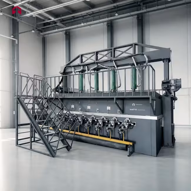
Horizontal Furnace - ToronFT™ HF
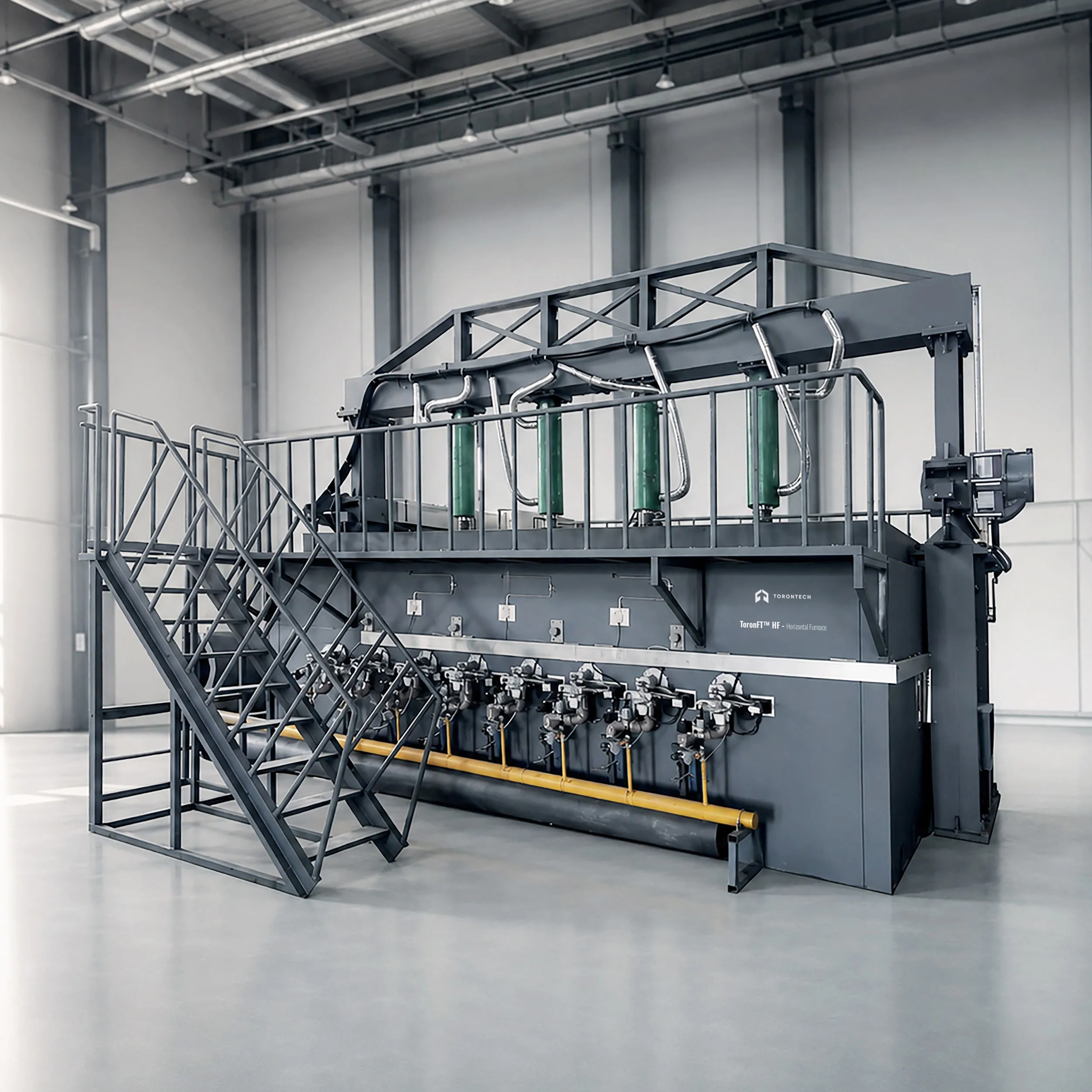
ToronFT™ HF horizontal furnace fire resistance testing subjects full-scale cable tray specimens to the standard time-temperature curve defined in ISO 834-1 and EN 1363-1, determining the fire resistance rating of cable management systems used in buildings, industrial plants, and critical infrastructure. The furnace accommodates cable tray assemblies in a horizontal orientation, matching the installed position in which trays support cables in ceilings, floor voids, and service corridors. Ten high-pressure LPG burners, each rated at 150 kW, drive the furnace interior temperature along the prescribed curve and maintain the precise pressure conditions required by the standard throughout the test.
The furnace chamber is constructed using American GOVMARK five-layer refractory technology, with an innermost layer of mullite high-temperature ceramic fibre rated to 1600°C and an outermost steel structural frame that remains at ambient temperature during operation. This layered wall construction delivers the thermal performance needed for sustained fire resistance tests while keeping external surface temperatures safe for laboratory personnel. The chamber interior measures 4.2 m deep by 2.0 m wide, giving laboratories the working area to test cable tray sections of realistic commercial dimensions along with the cables and fittings loaded onto them.
A PLC-based computer control system drives the full test sequence, from automated burner ignition through temperature curve tracking, pressure regulation, and data logging. The system captures furnace temperature from ten K-type thermocouples and furnace pressure from three differential pressure transducers at three readings per second, continuously comparing measured values against the ISO 834-1 time-temperature curve and adjusting burner output and pressure relief fan speed accordingly. Test records save automatically with timestamp and test identification, and the data can be exported to Excel for report generation. An integrated continuity monitoring circuit checks cable electrical integrity throughout the fire exposure, with test voltage adjustable from 0 to 1000 V phase voltage.
Horizontal Furnace - ToronFT™ HF Applications
The ToronFT™ HF serves laboratories and testing bodies that need to qualify cable tray systems for fire resistance ratings under internationally recognised standards. It covers the full range of cable management products that require horizontal furnace testing.
- Cable Tray and Cable Ladder Manufacturers: fire resistance classification testing of steel, aluminium, and composite cable tray systems to obtain fire resistance ratings for product approval and building code compliance.
- Accredited Fire Testing Laboratories: third-party qualification and certification testing of cable management systems per ISO 834-1, EN 1363-1, and equivalent national standards on behalf of manufacturers.
- Building and Construction Projects: testing cable tray assemblies specified for high-rise buildings, hospitals, airports, and data centres where fire resistance ratings are mandated by fire safety codes.
- Nuclear and Power Generation Facilities: qualification testing of cable support systems in safety-critical environments where cable trays must maintain structural and functional integrity for defined fire durations.
- Industrial and Petrochemical Plants: fire resistance testing of cable management systems routed through process areas where hydrocarbon fire exposure is a design consideration.
- Fire Protection Material Developers: evaluation of intumescent coatings, fire blankets, and protective wraps applied to cable tray systems to verify their contribution to the fire resistance rating of the assembly.
- Research Institutions and Universities: investigation of thermal behaviour of building elements, refractory materials, and passive fire protection systems under controlled standard fire conditions.
- Construction Product Certification Bodies: furnace testing of structural and non-structural building elements as part of product approval schemes requiring fire resistance performance data.
Standards
The ToronFT™ HF is designed to satisfy the furnace construction, instrumentation, and test procedure requirements of the following international fire resistance testing standards.
- ISO 834-1 - Fire-Resistance Tests: Elements of Building Construction - Part 1: General Requirements
- EN 1363-1 - Fire Resistance Tests: Part 1: General Requirements
- EN 1363-2 - Fire Resistance Tests: Part 2: Alternative and Additional Procedures
- IEC 61537 - Cable Management: Cable Tray Systems and Cable Ladder Systems (fire performance requirements)
- ASTM E119 - Standard Test Methods for Fire Tests of Building Construction and Materials
- BS 476-20 - Fire Tests on Building Materials and Structures: Method for Determination of the Fire Resistance of Elements of Construction (General Principles)
Horizontal Furnace - ToronFT™ HF Key Features
The ToronFT™ HF integrates large-chamber horizontal furnace capacity with precision multi-zone temperature control, automated pressure regulation, and comprehensive data acquisition in a system engineered for professional fire resistance testing laboratories.
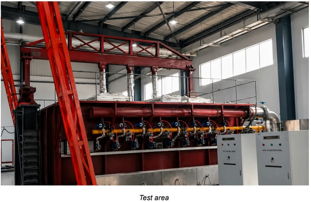
- 4.2 m × 2.0 m Horizontal Test Chamber: a working chamber sized for full commercial cable tray sections and loaded cable assemblies, accommodating the specimen dimensions typically required for fire resistance classification testing.
- Five-Layer GOVMARK Refractory Construction: furnace walls built using American GOVMARK technology combine a 1600°C-rated mullite ceramic fibre inner layer, refractory brick, high-temperature mineral wool, fired brick outer casing, and steel structural frame, holding the exterior surface at ambient temperature during operation.
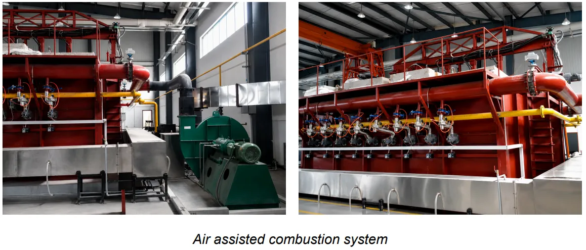
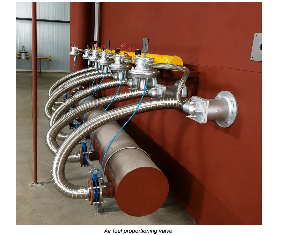
- Ten Independent 150 kW LPG Burners: each burner operates on its own fuel and air line with an air-fuel ratio valve, distributing heat uniformly across the full chamber length and allowing the control system to fine-tune zone temperatures for consistent curve tracking.
- Automated ISO 834-1 Curve Tracking: the PLC control system compares the ten-thermocouple average against the target curve every three seconds and adjusts burner output continuously, maintaining the required temperature tolerance from ignition through the full test duration.
- Three-Transducer Pressure Measurement and Control: three T-probe differential pressure transducers provide redundant furnace pressure measurement, with one transducer actively controlling the pressure relief fan speed and the second serving as a cross-check reference, as required by ISO 834-1.
- Dual-Mode Flue Gas Cooling: exhaust gases pass through simultaneous air-fan and water-spray cooling in a 3 m cooling duct, dropping flue gas temperature below 70°C before discharge and protecting downstream infrastructure.
- 16-Bit High-Precision Data Acquisition at 3 s Intervals: a 16-bit acquisition card records temperature from all ten furnace thermocouples, furnace pressure from three transducers, and circuit integrity status three times per second, with all data time-stamped and stored for test report generation.
- 0 to 1000 V Adjustable Cable Circuit Continuity Check: a three-phase isolation transformer with variable output applies live test voltage to cable conductors throughout the furnace test, with 3 A or 5 A per conductor current and a Type D II fuse circuit that triggers on insulation failure.
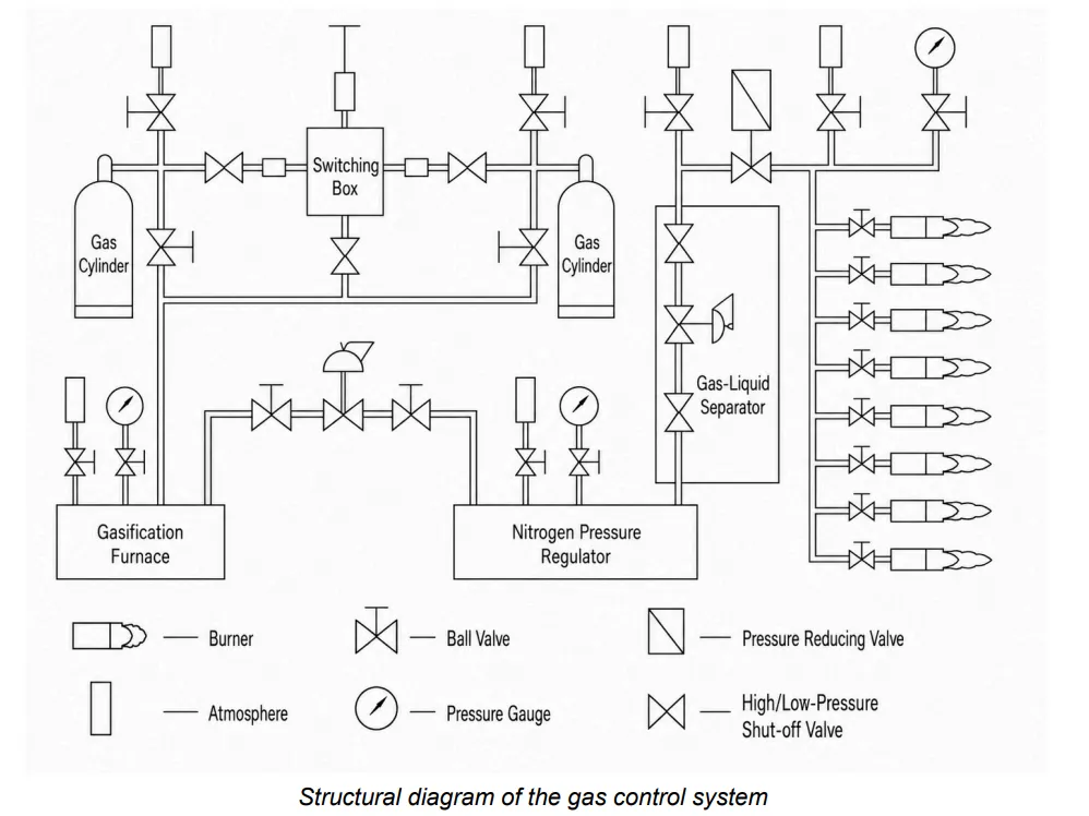
- Automated LPG Switchover System: eight LPG cylinders arranged in two groups of four allow automatic liquid-phase switching when one group drops below the pressure setpoint, preventing gas interruption and test abort during long fire exposure periods.
- PC Software with Excel Export and Lifetime Free Upgrades: the LabVIEW-based operator interface displays live temperature curves, pressure readings, and specimen data with real-time graphing; test records save by test number and can be exported to Excel or reprinted from stored data at any time; software upgrades are provided at no charge.
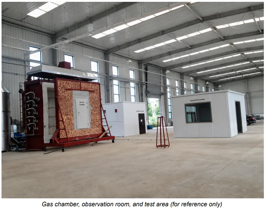
- Observation Port and Gas Leak Detection: a rear-wall observation port allows the test operator to view the specimen face and flame conditions during the test; two combustible gas detectors monitor the gas room and test area for LPG leaks, with automatic fuel shutoff on alarm.
Theory and Method
Fire resistance testing measures the time a building element can contain or resist a fire before it fails a defined criterion, whether structural collapse, loss of integrity, or excessive heat transmission to the unexposed face. The ISO 834-1 standard fire follows the cellulosic time-temperature relationship T = 345 × log₁₀(8t + 1) + 20, where T is the average furnace temperature in degrees Celsius and t is the elapsed test time in minutes. This curve was derived from observations of real building fires and ramps furnace temperature from ambient to approximately 945°C at 60 minutes and to around 1049°C at 120 minutes, representing the sustained thermal attack of a fully developed compartment fire on a structural or protective element.
The ToronFT™ HF maintains the standard curve by continuously adjusting the fuel-to-air ratio across ten 150 kW LPG burners. Each burner receives an independently regulated gas line and combustion air feed from the 11 kW forced-air system, with an air-fuel ratio valve on every burner controlling the mix to achieve complete combustion and maximum heat release. Ten K-type armoured thermocouples, arranged five per side with probe tips projecting 25 mm from the thermocouple sheath into the furnace space, measure the average furnace temperature at the locations and heights specified by ISO 834-1. The control software compares the ten-thermocouple average against the target curve every three seconds and adjusts burner firing rates through the PLC, maintaining furnace temperature within the tolerances specified in the standard.
Furnace overpressure is an equally important test parameter. ISO 834-1 specifies that the positive pressure at the top of the furnace opening must reach 15 ± 5 Pa within five minutes of test start and hold at 17 ± 3 Pa from ten minutes onward. Three T-probe differential pressure transducers, manufactured from USU310S stainless steel capable of withstanding temperatures above 1300°C in the furnace section, measure furnace gauge pressure relative to the laboratory atmosphere at the same horizontal level. The 7.5 kW pressure relief fan, controlled by a variable-frequency drive, adjusts exhaust flow to maintain the pressure setpoint continuously.
Exhaust gases leaving the furnace pass through 330 mm diameter high-temperature stainless steel ducting and then through a water spray cooling section that reduces flue gas temperature to below 70°C before discharge, protecting downstream ductwork and meeting ventilation safety requirements.
Horizontal Furnace - ToronFT™ HF Technical Specifications
| Parameter | Specification |
|---|---|
| Product Name | Horizontal Furnace |
| Model | ToronFT™ HF |
| Applicable Standards | ISO 834-1, EN 1363-1, EN 1363-2, IEC 61537, ASTM E119, BS 476-20 |
| Furnace Orientation | Horizontal (specimen loaded horizontally) |
| Furnace Interior Dimensions | 4.2 m (depth) × 1.5 m (height) × 2.0 m (width) |
| Maximum Furnace Temperature | 1300°C (inner layer rated to 1600°C) |
| Furnace Wall Construction | Five-layer: (1) steel structural frame, (2) external fired brick, (3) high-temperature mineral wool, (4) refractory brick, (5) mullite ceramic fibre (1600°C rated) |
| Furnace Exterior Temperature | Ambient (outer surface does not heat during operation) |
| Fuel | LPG (liquefied petroleum gas), 50 kg cylinder supply; pipeline gas also compatible |
| LPG Supply Configuration | 8 cylinders; 2 groups of 4 cylinders in parallel; automatic liquid-phase switchover between groups |
| Fuel Consumption | 75 to 125 m³/h |
| Burner Type | High-pressure LPG burners with air-fuel ratio control |
| Number of Burners | 10 |
| Burner Power | 150 kW per burner |
| Total Burner Power | 1500 kW |
| Ignition Method | Automatic high-voltage electronic ignition; flame-out detection with automatic alarm and fuel cutoff |
| Air-Fuel Ratio Control | Proportional air-fuel valve on each burner for optimised combustion; 11 kW combustion air fan |
| LPG Vaporiser | Gas-phase vaporiser converts liquid LPG to vapour to maximise cylinder utilisation and ensure stable combustion |
| Furnace Temperature Measurement | 10 × K-type armoured thermocouples, 2.0 mm diameter, per ISO 834-1; 5 on each side; probe tip projection 25 mm; temperature accuracy ±15°C in furnace |
| Thermocouple Acquisition Points | 10 active channels (plus 2 spare) |
| Thermocouple Temperature Range | Up to 1300°C |
| Furnace Pressure Measurement | 3 × T-probe differential pressure transducers, USU310S high-temperature stainless steel; range 0–100 Pa; accuracy ±0.5 Pa; one control, one verification |
| Furnace Pressure Control Target | 15 ± 5 Pa at furnace top (first 5 min); 17 ± 3 Pa (from 10 min onward) per ISO 834-1 |
| Furnace Pressure Accuracy | ±3 Pa |
| Overpressure Protection | Automatic gas shutoff and test termination if furnace pressure exceeds 100 Pa |
| Pressure Relief Fan | 7.5 kW high-temperature centrifugal fan with variable-frequency drive; computer-controlled exhaust volume |
| Smoke Exhaust Ducting (In-Furnace) | 330 mm diameter USU310S stainless steel; rated to 1300°C; two exhaust ports on rear furnace wall |
| Exhaust Gas Cooling | Dual-mode: forced-air fan plus water-spray cooling in 3 m cooling duct; exhaust temperature at outlet ≤70°C |
| Smoke Collection Tower | Conical collection tower above furnace opening; 300 mm diameter ducting to pressure relief system; 7.5 kW high-temperature induced draft fan |
| Data Acquisition Rate | 3 readings per second (once every 3 s) |
| Pressure Data Logging | Recorded every 5 minutes; acquisition at 3 readings/s |
| Data Acquisition Hardware | 16-bit high-precision data acquisition card; Delta PLC (Taiwan); multi-channel temperature transmitter modules |
| Control Software | LabVIEW-based; Windows operating system; OPC-compatible open architecture; real-time and historical curve display; Excel export; lifetime free upgrades |
| Control Interface | PC (computer control); displays temperature curves, pressure, specimen thermocouple data; one-click report generation and print |
| Time Accuracy | ±1 s/h |
| Temperature Accuracy – Furnace | ±15°C |
| Temperature Accuracy – Unexposed Face / Ambient | ±2.5°C |
| Circuit Continuity Test Voltage | 0 to 1000 V (phase voltage), continuously adjustable |
| Circuit Continuity Test Current | 3 A or 5 A per conductor or conductor group |
| Circuit Continuity Fuse | 3 A, Type D II |
| Voltage | 3-phase 5-wire, AC 380 V, 50 Hz |
| Total Installed Power | 35 kW (including smoke extraction system) |
| Water Supply | Mains supply required (for exhaust gas cooling) |
| Gas Leak Detection | 2 combustible gas detectors (gas room and test area); automatic fuel shutoff on alarm |
| Minimum Floor-to-Ceiling Height | 7.0 m |
| Total Laboratory Floor Area Required | 275 m² minimum (test area, control room, gas room, sample preparation area) |
| Observation Port | Rear furnace wall observation window for direct visual monitoring of specimen and flame during test |
Standard Configuration
| Item | Description |
|---|---|
| Horizontal Fire Resistance Furnace | 1 unit, five-layer refractory construction, 4.2 m × 1.5 m × 2.0 m interior |
| LPG Burner System | 10 × 150 kW high-pressure burners with air-fuel ratio valves, ignition controllers, and flame-out detectors |
| Gas Control System | LPG vaporiser, two-group automatic cylinder switchover, dual-stage pressure regulators, motorised butterfly valves, proportional valves, pressure gauges, gas-liquid separator, gas leak detector |
| Combustion Air System | 11 kW forced-air fan, 330 mm main air manifold with branch feeds to each burner |
| Pressure Relief and Exhaust System | 7.5 kW variable-speed exhaust fan, 330 mm USU310S high-temperature stainless steel furnace ducting, dual air-fan and water-spray exhaust cooler |
| Smoke Collection System | PPCI conical collection tower above furnace opening, 7.5 kW induced draft fan, 300 mm collection duct |
| Temperature Measurement System | 10 K-type armoured thermocouples (2 spare), multi-channel temperature transmitter modules, 16-bit acquisition card |
| Pressure Measurement System | 3 T-probe differential pressure transducers, 2 high-precision pressure transmitters, USU310S stainless steel probe tubes |
| Computer Control System | Delta PLC, PC workstation, LabVIEW control software, real-time data logging and report generation |
| Circuit Continuity System | Three-phase isolation transformer, variable voltage regulator (0–1000 V), load resistors, fuse protection |
Facility Requirements (Customer Supplied)
| Requirement | Specification |
|---|---|
| Electrical Supply | 3-phase 5-wire, AC 380 V, 50 Hz, 35 kW dedicated circuit with independent circuit breaker |
| LPG Cylinders | 8 × 50 kg LPG cylinders (4 per group, 2 groups); additional cylinder stock for test duration |
| Water Supply | Mains cold water connection for exhaust cooling |
| Laboratory Space | Minimum 275 m² total; minimum 7.0 m floor-to-ceiling height in test area |
| Ventilation | Good ventilation in test area; no flammable or explosive materials in vicinity |
| Exhaust Ducting | External flue connection for cooled exhaust gases |